Detection of grounding strap breakage

a grounding strap and detection technology, applied in the field of plasma processing chambers, can solve the problems of aluminum grounding strap weakening, breaking, and new challenges in handling and production

Active Publication Date: 2015-08-06
APPLIED MATERIALS INC
View PDF1 Cites 7 Cited by
  • Summary
  • Abstract
  • Description
  • Claims
  • Application Information

AI Technical Summary

Benefits of technology

[0012]In another embodiment, a computer-readable medium is disclosed that includes instructions that enable a processing unit to implement one or more aspects of the disclosed method for detecting ground strap breakage. The method includes monitoring real-time RF generated data created while a plasma is formed in the processing chamber. The method also includes comparing the real-time RF generated data with a pre-determined threshold plasma processing characteristic, such as measured RF related data. The method includes generating an alert if the measured real-time RF related data meets or exceeds the pre-determined threshold plasma processing characteristic (e.g., RF power delivery related data). The RF related data may include RF frequency, direct current (DC) voltage, peak-to-peak voltage, and/or RF reflected power.
[0013]In yet another embodiment, a system is disclosed having a processor, memory, and application programs configured to implement one or more aspects of the disclosed method for detecting grounding strap breakage in a processing chamber. The system includes a processor and a plasma processing chamber. The plasma processing chamber includes a plurality of chamber walls that at least partially define a processing region and a substrate support disposed within the processing region. The plasma processing chamber also includes a plurality of g

Problems solved by technology

This growth in the size of the large area substrates has presented new challenges in handling and production.
As the substrate support moves up and down, coupled with high processing temperatures (e.g., greater than 300 degrees Celsius), the aluminum grounding straps weaken due to thermal stress and eventually break.
Since the grounding straps are not readily visible from the e

Method used


Image

  • Detection of grounding strap breakage
  • Detection of grounding strap breakage
  • Detection of grounding strap breakage

Examples


Embodiment Construction

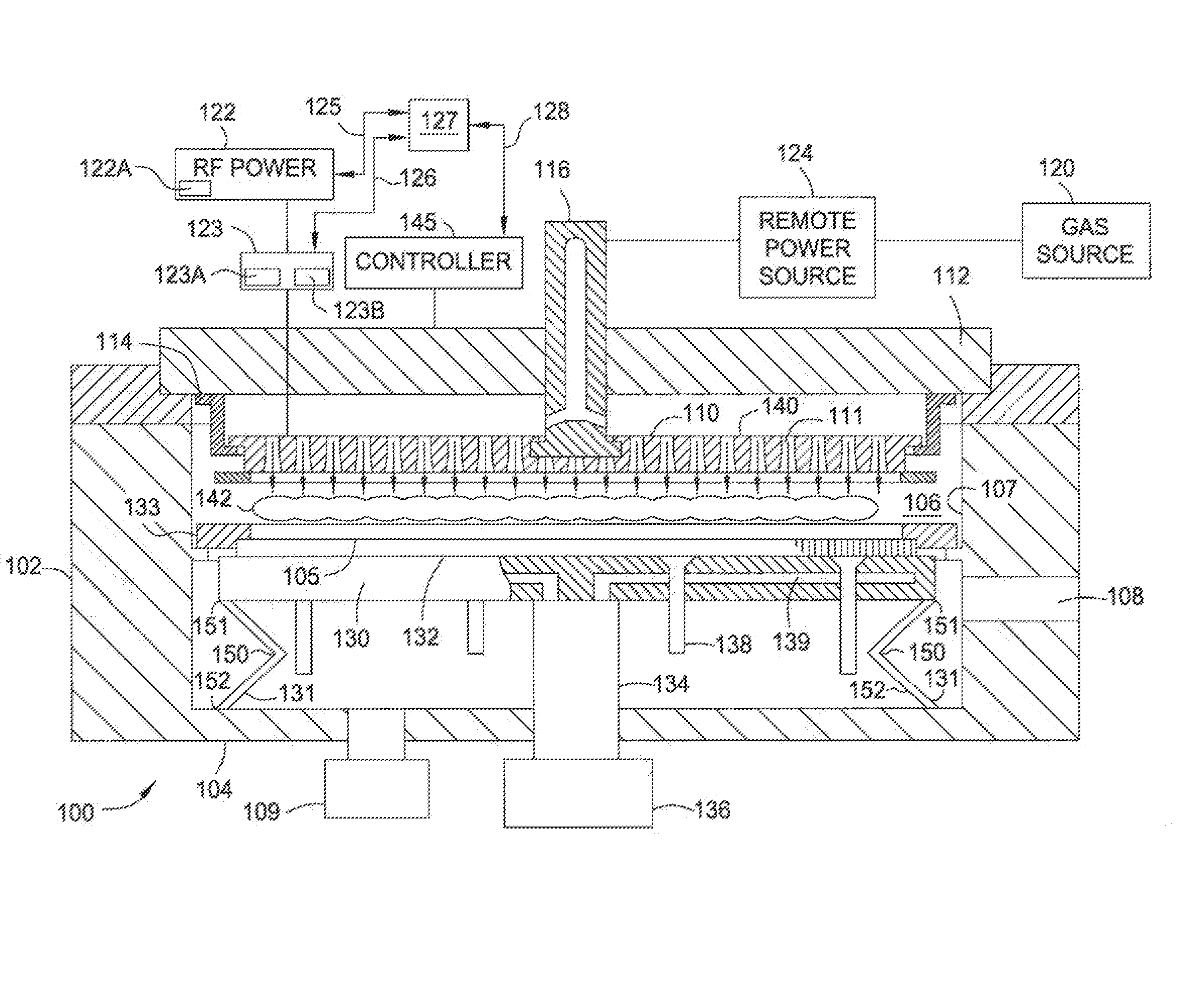
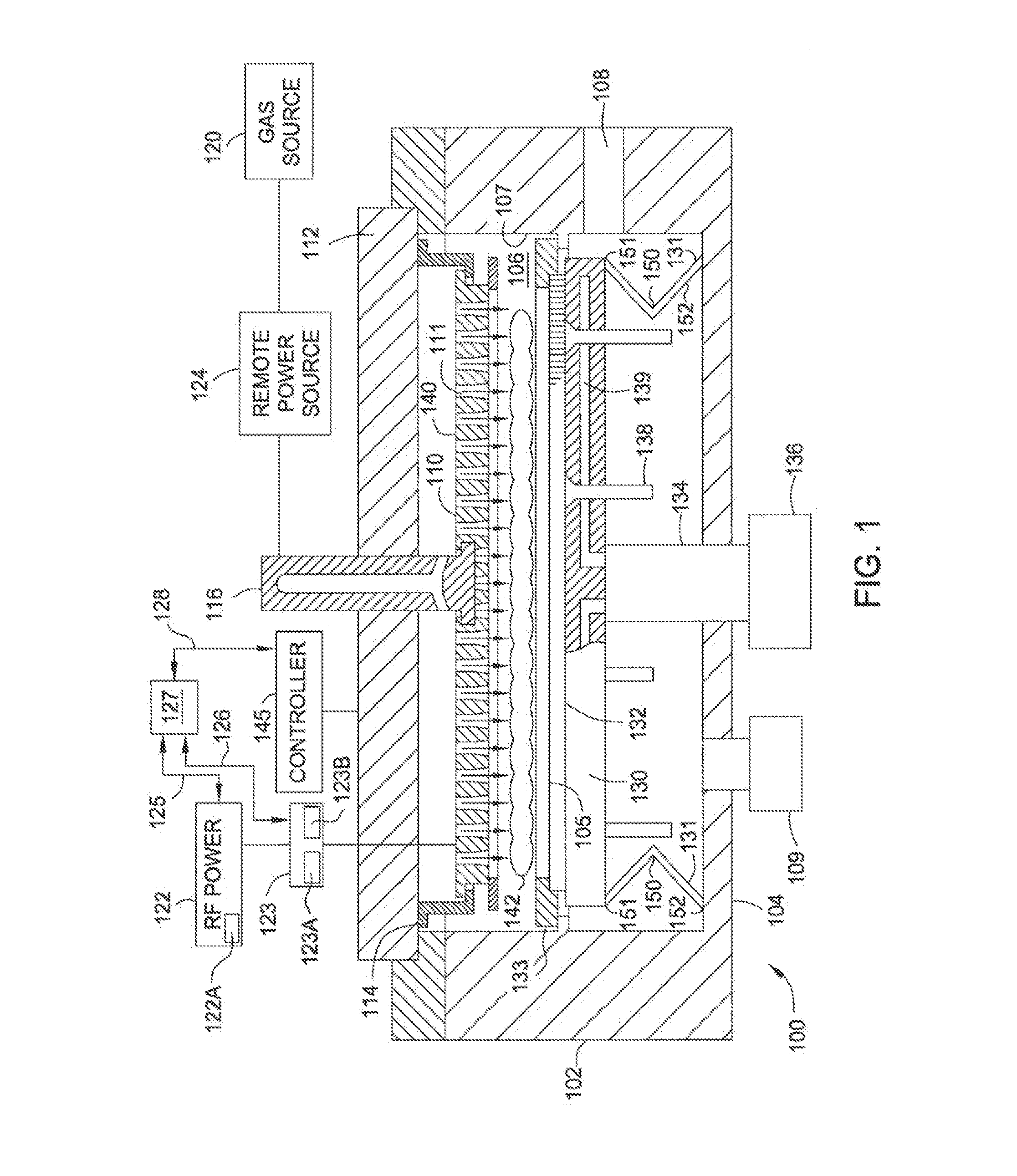
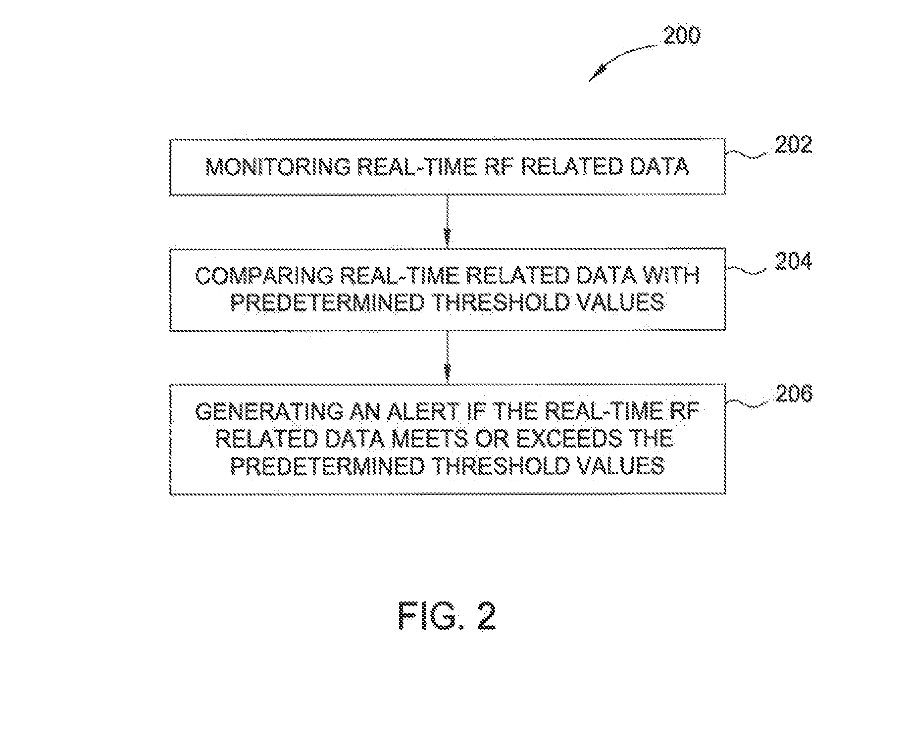
[0018]The embodiments presented herein relate to a method for detecting the breakage of one or more grounding straps in a plasma processing chamber. The grounding straps are coupled to a substrate support and / or substrate supporting components disposed in a plasma processing chamber. The breakage of the grounding straps may be detected while a plasma process is being performed in the plasma processing chamber without opening the processing chamber. Also, by use of one or more of the methods described herein, a user may be alerted that one or more of the grounding straps have become damaged or broken.

[0019]Embodiments herein are illustratively described below in reference to a PECVD system configured to process large area substrates, such as a PECVD system, available from the AKT division of Applied Materials, Inc., Santa Clara, Calif. However, it should be understood that the invention may have utility in other plasma processing chambers where it is desirable to ensure that one or m...


PUM

PropertyMeasurementUnit
Threshold limitaaaaaaaaaa
Electric impedanceaaaaaaaaaa

Abstract

The present invention generally relates to a method for detecting the breakage of one or more grounding straps without stopping processing or opening the processing chamber for inspection. In one embodiment, a method for detecting grounding strap breakage in a processing chamber includes monitoring real-time RF related data from plasma generated in the processing chamber. The method also includes comparing the real-time RF related data with a pre-determined threshold RF related data. The method includes generating an alert if the real-time RF related data meets or exceeds the pre-determined threshold RF related data. In one embodiment, the RF related data includes RF frequency, direct current voltage, voltage peak-to-peak, and/or RF reflected power.

Description

CROSS-REFERENCE TO RELATED APPLICATIONS[0001]This application claims priority to U.S. Provisional Patent Application Ser. No. 61 / 935,837, filed on Feb. 4, 2014, which herein is incorporated by reference.BACKGROUND[0002]1. Field of the Invention[0003]Embodiments of the invention generally relate to a plasma processing chamber having a RF return path with low impedance and the method for using the same.[0004]2. Description of the Related Art[0005]Liquid crystal displays (LCDs) or flat panels are commonly used for active matrix displays such as computers, touch panel devices, personal digital assistances (PDAs), cell phones, television monitors, and the like. Further, organic light emitting diodes (OLEDs) have also been widely used for flat panel displays. Generally, flat panels comprise two plates having a layer of liquid crystal material sandwiched therebetween. At least one of the plates includes at least one conductive film disposed thereon that is coupled to a power source. Power,...

Claims


Application Information

Patent Timeline
IPC IPC(8): H01J37/32C23C16/505C23C16/458G01R31/02C23C16/52
CPCH01J37/32935G01R31/024C23C16/505C23C16/458C23C16/52H01J37/32174H01J37/32944H01J37/3299
Inventor ILIOPOULOS, ILIASNA, SHUOYANCY, KELBYCHEN, CHUNSHENG
Owner APPLIED MATERIALS INC
Why Eureka
Try Eureka