
Internal shield splice

a shield and shielding technology, applied in the direction of coupling device connection, coupling device details, connection contact member materials, etc., can solve the problems of difficult and time-consuming termination and grounding of each shield individually, adversely affecting the operation of the equipment,

Inactive Publication Date: 2001-09-11
ICORE INT
View PDF3 Cites 7 Cited by
  • Summary
  • Abstract
  • Description
  • Claims
  • Application Information

AI Technical Summary

Problems solved by technology

The braided metal shield is often required: despite the layers protecting the conductive material, electronic equipment powered and controlled through such wires is often vulnerable to electromagnetic interference (EMI), which adversely affects the operation of the equipment.
When multiple internal wires, or wire bundles, are spliced together to join cables or to connect cables to electronic components, it can be difficult and time consuming to terminate and ground each shield individually.

Method used


Image

  • Internal shield splice
  • Internal shield splice

Examples


Embodiment Construction

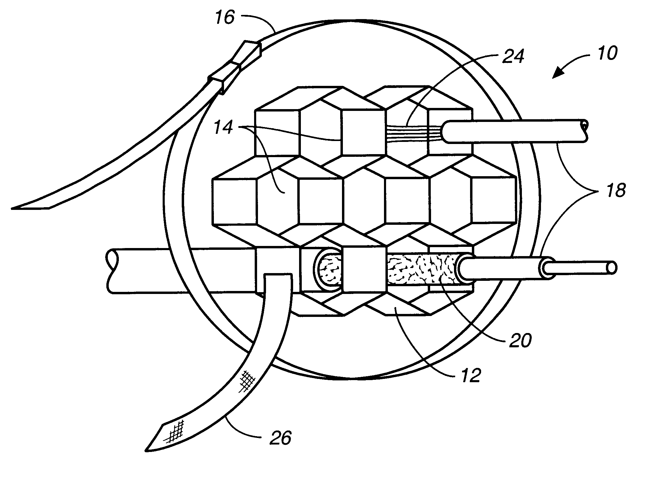
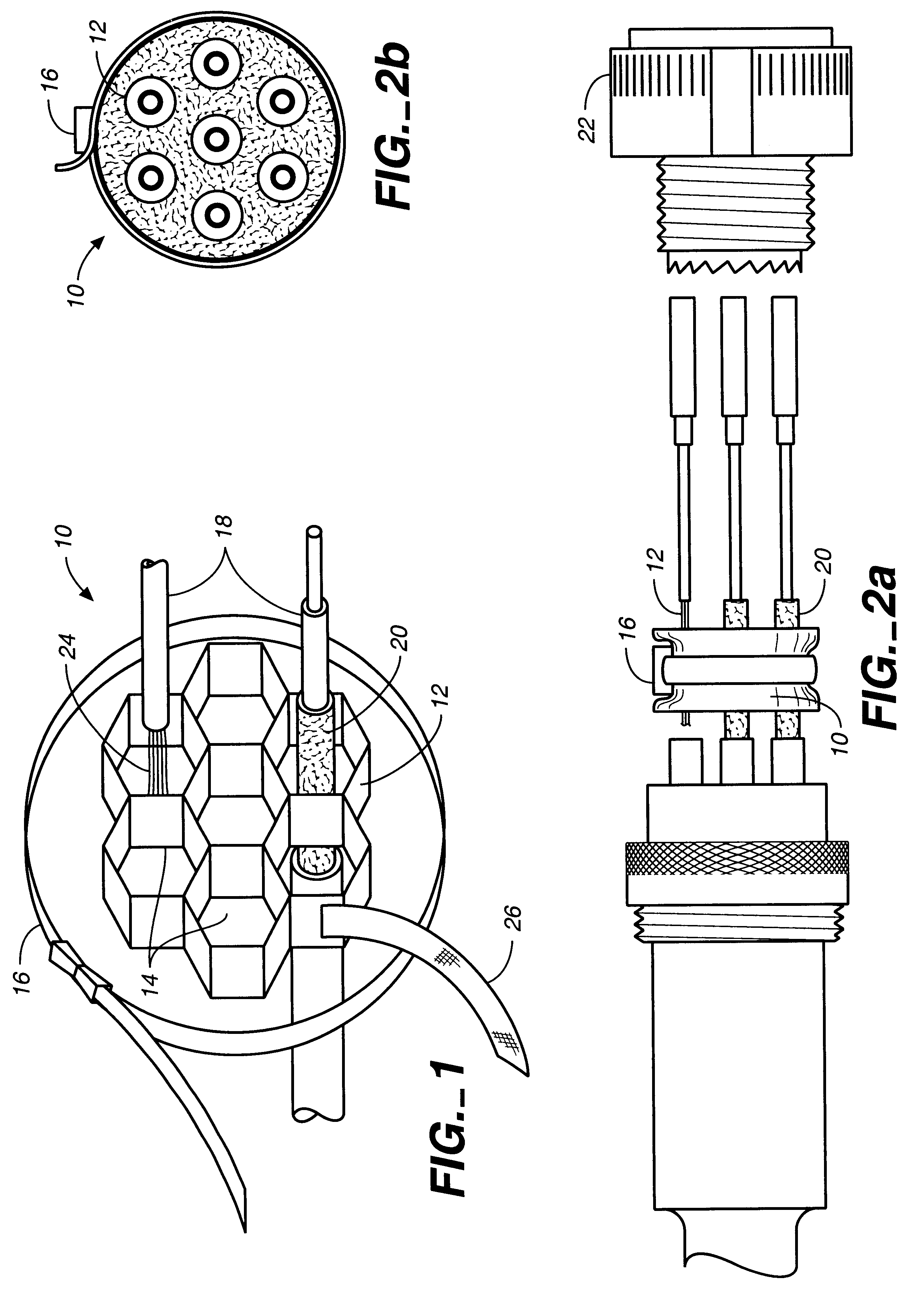
FIG. 1 is a perspective view of the shield splice 10 of the present invention. The splice comprises a sleeve 12, preferably fabricated of very thin aluminum or tin plated copper metal. The material is easily deformable transversely so that it can be easily crushed or crumpled, but it is of high electrical conductivity and preferably high tensile strength. If the segment of sleeve is relatively short, it may have the configuration of a ring or ferrule. A longer sleeve segment may have a generally cylindrical configuration, as depicted in FIGS. 1 and 2a. The interior of the sleeve defines a plurality of passages 14, which may have any of a number of different geometrical shapes, including hexagonal (honeycomb shaped), triangular, square, or circular. FIG. 1 shows the splice having honeycomb apertures and an external configuration defined by the distal exterior exposed surfaces of the honeycombs. Viewed in cross section, the external surface of the splice is regular and substantially c...


PUM


Abstract

A shield splice for terminating the individual shields on individual wires in multiple wire bundles includes a generally elongate section of transversely deformable material, preferably fabricated from aluminum or tin plated copper metal. The elongate section is open at each end and has a plurality of longitudinal passages which may be any of a number of geometrical shapes. The exterior surface is surrounded by a stainless steel or plastic tie strap, which may have a preinstalled ground strap. In use, wires with exposed shields are inserted through the passages in the elongate section, and the tie strap is cinched down and tightened, thus crushing the splice material around the individual wire shields and grounding them collectively. A method for grounding multiple internal braid splices is also disclosed.

Description

1. Field of the InventionThe present invention relates to an apparatus for electrically terminating shielded electrical wires, and more particularly to an internal braid splice for electrically terminating individual shields on multiple internal wires and which may be installed without the use of tools.2. Description of the Prior ArtShielded wire commonly comprises a plurality of concentric layers of material, usually including a metal conductor, an insulating tube or sleeve surrounding the conductor, a braided metal shield (or foil or other shielding material) wrapped around the insulting sleeve, and a second insulating layer surrounding the shield. The braided metal shield is often required: despite the layers protecting the conductive material, electronic equipment powered and controlled through such wires is often vulnerable to electromagnetic interference (EMI), which adversely affects the operation of the equipment. EMI can be generated by nearby electronic components or from ...

Claims


Application Information

Patent Timeline
IPC IPC(8): H01R9/05H01R13/658
CPCH01R13/65802H01R9/0512H01R13/658
Inventor GOETT, EDWARD P.
Owner ICORE INT
Learn More