Rotation sensor, and method for outputting signals from rotation sensor

a technology of rotation sensor and signal output, which is applied in the field of rotation sensor, can solve the problems of difficult to obtain a stable information transmission speed, one of the foregoing cannot be constantly monitored,

Inactive Publication Date: 2008-12-16
AISIN SEIKI KK
View PDF13 Cites 17 Cited by
  • Summary
  • Abstract
  • Description
  • Claims
  • Application Information

AI Technical Summary

Benefits of technology

[0008]It is an object of the present invention to provide a rotation sensor enabling stable information transmission that is not dependent on the rotation speed of a rotor and a method for outputting a signal from the rotation sensor.
[0010]Unlike the prior art, in the present invention, information signal representing information other than the rotation direction of the rotor is output to the wire as a carrier wave obtained through modulation in a state superimposed with the pulse so that the information signal is not dependent on the pulse frequency representing the rotation speed of the rotor. This realizes stable information transmission that is not dependent on the rotation speed of the rotor.
[0012]In the present invention, the modulation unit modulates the plurality of information signals into a plurality of carrier waves having different frequencies that are higher than the frequency of the pulse signal. Accordingly, even if, for example, the information signal has a large amount of information, the information signal is divided into a plurality of information signals. By modulating the divided information signals into a plurality of carrier waves, the information amount that is simultaneously transmitted by the rotation sensor is increased. Further, for example, by changing the number of modulated carrier waves in accordance with the increase or decrease in the information amount of the information signal, the real time applicable capacity with respect to an increase in the information amount that is to be transmitted may be improved. Further, when there are plural types of information signals, the information signal may be modulated into different carrier waves. In this case, the information that is to be transmitted may be selected by selectively modulating the information signal corresponding to the required information into the corresponding carrier wave. That is, information signal corresponding to certain information may constantly be modulated into a corresponding carrier wave, and an information signal corresponding to other information may intermittently, in a periodic or non-periodic manner, be modulated into the corresponding carrier wave. In this manner, the rotation sensor may transmit selected information.
[0013]The rotation sensor may further include an acquisition unit for acquiring the information signal from an external information source. In the present invention, by acquiring the information signal from the external information source with the rotation sensor, the information signal is output to the wire as a whole. Accordingly, the external information source does not have to be wired for output of the information signal, and the necessary number of wires is reduced. The rotation sensor may detect the rotation speed of a vehicle wheel. The information signal may be a signal from a vehicle height sensor.
[0015]The modulation unit may modulate the information signal and generate a carrier wave of 100 KHz to 10 MHz. The modulation unit may intermittently modulate the information signal into the carrier wave. The modulation unit may modulate the information signal by performing amplitude modulation to generate the carrier wave. In this case, the circuit configuration of the modulation unit is simplified. The modulation unit may modulate the information signal by performing frequency modulation to generate the carrier wave. In this case, the circuit configuration is simplified in comparison with when phase modulation is employed, and the reliability of information transmission is improved in comparison to when amplitude modulation is employed. The modulation unit may modulate the information signal by performing phase modulation to generate the carrier wave. In this case, the noise resistance during information transmission is improved.

Problems solved by technology

Thus, one of the foregoing cannot be constantly monitored.
Thus, it is difficult to obtain a stable information transmission speed (communication speed).

Method used


Image

  • Rotation sensor, and method for outputting signals from rotation sensor
  • Rotation sensor, and method for outputting signals from rotation sensor
  • Rotation sensor, and method for outputting signals from rotation sensor

Examples


first embodiment

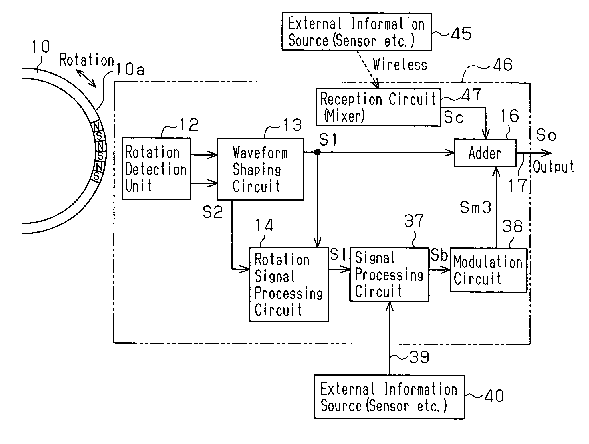
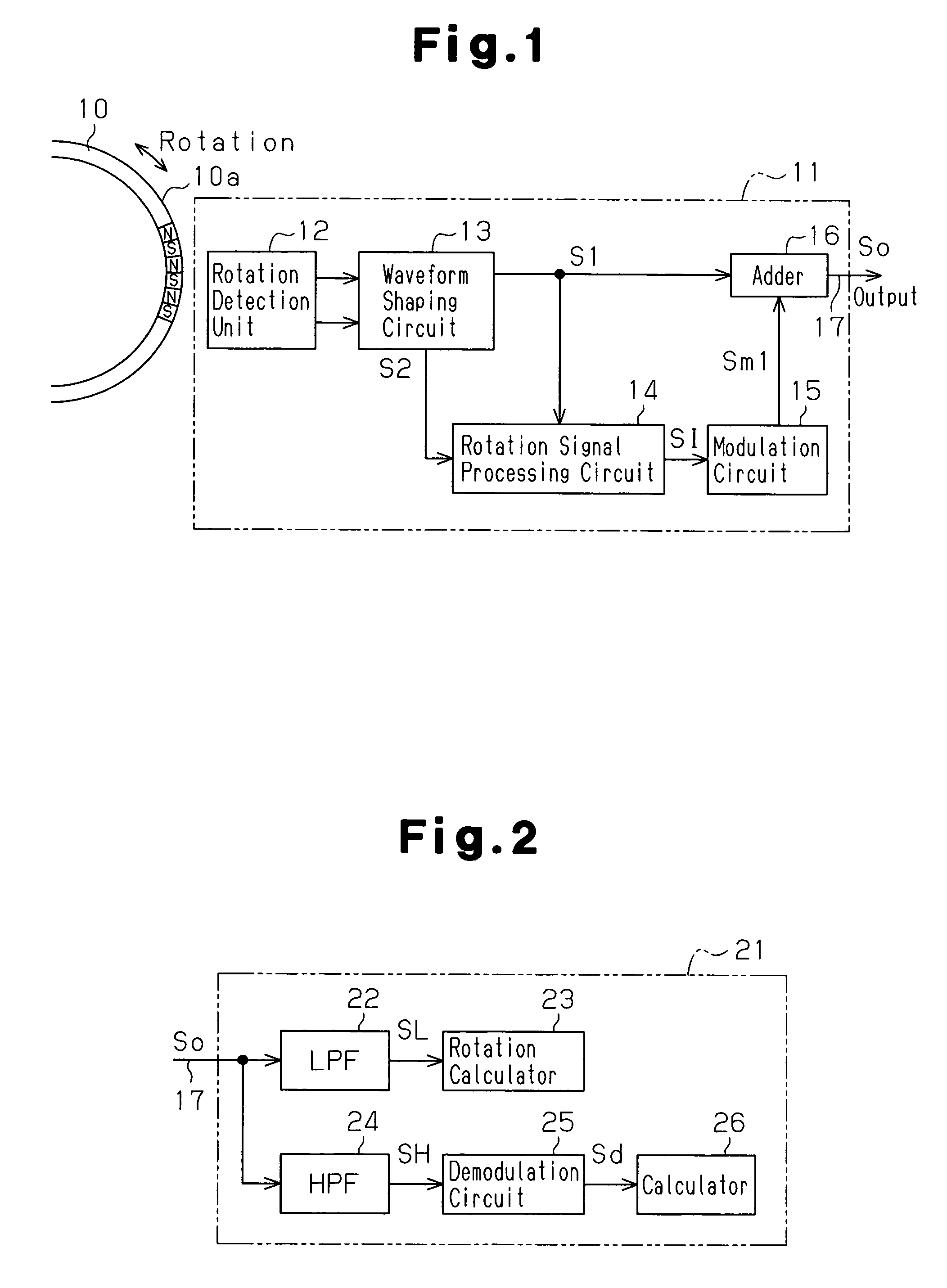
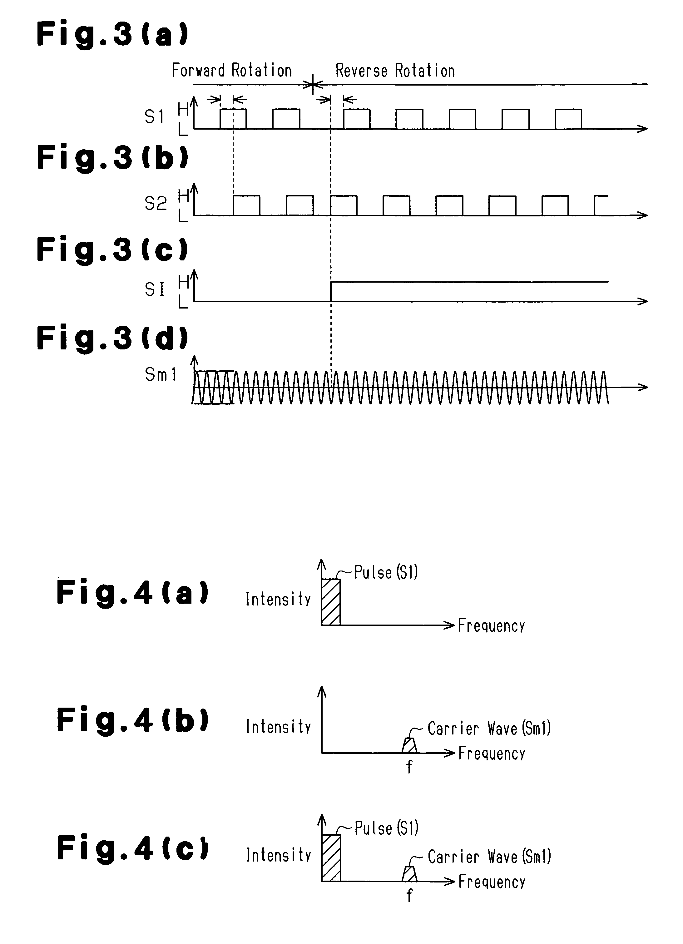
[0026]A rotation sensor according to the present invention for detecting the rotation speed and rotation direction of a wheel for an automobile or the like will now be discussed with reference to FIGS. 1 to 4(d). FIG. 1 is a block diagram of a rotation sensor 11 for detecting rotation of a rotor 10, which is a detection subject. FIG. 2 is a block diagram of a controller 21 that receives a signal from the rotation sensor 11 via a wire (connection wire). FIGS. 3(a) to 3(d) are time charts for output signals generated by various types of circuits incorporated in the rotation sensor 11. FIGS. 4(a) to 4(c) are schematic diagrams showing the relationship between the frequency and intensity of these output signals.

[0027]As shown in FIG. 1, the rotor 10 has a peripheral portion defining a magnetic portion 10a in which N poles and S poles switch every predetermined angle. The rotor 10 rotates integrally with the wheel. The rotation sensor 11 is arranged facing towards the magnetic portion 10...

third embodiment

[0067]The adder 16 superimposes the pulse signal S1 from the waveform shaping circuit 13 with the modulated wave Sm4 and sends the output signal So to the output wire 17. Since this is performed in the same manner as in the third embodiment, this will not be described in detail.

[0068]The output signal So output via the output wire 17 is processed by a controller corresponding to the controller of the third embodiment. The controller of the present embodiment extracts the desired information (information signals SI, SI3, and SI4) by dividing the information signal Sd (refer to FIG. 2), which passes through the HPF 24 to be demodulated by the demodulation circuit 25, in accordance with a predetermined standard. As a result, the calculator 26 of the controller acquires rotation direction information of the rotor 10 and external information.

[0069]As described above, in addition to the advantages of the third embodiment, the present embodiment has the advantage described below.

[0070](1) ...

second embodiment

[0076]The output signal So output via the output wire 17 is processed by a controller corresponding to that of the In lieu of the HPF 24, the controller includes a bandpass filter (BPF), which enables passage of a signal in the high frequency band centered about the frequency f, and a BPF, which enables passage of a signal in the high frequency band centered about the frequency fm. The controller includes a plurality of demodulation circuits 25 for separately demodulating these band passage signals. Thus, the controller acquires the rotation direction of the rotor 10, the external information via the external wire 39, and the external information acquired through wireless communication by the rotation sensor 46.


PUM


Abstract

A rotation sensor for outputting a pulse signal, which has a frequency corresponding to a rotation speed of a rotor, to a wire. The rotation sensor includes a modulation unit and an output unit. The modulation unit modulates an information signal representing information other than the rotation speed into a carrier wave having a frequency higher than the frequency of the pulse signal. The output unit superimposes and outputs to the wire the pulse signal and the carrier wave. Accordingly, the rotation sensor performs stable information transmission that is not dependent on the rotation speed of the rotor.

Description

FIELD OF THE INVENTION[0001]The present invention relates to a rotation sensor for outputting a pulse signal representing rotation speed of a rotor and a method for outputting a signal from a rotation sensor.[0002]This is a National Stare entry of International Application PCT / JP2005 / 002747, with an international filing date of Feb. 21, 2005, which was published as WO 2005 / 080995 A1, and the complete disclosure of which is incorporated into this application by reference.BACKGROUND OF THE INVENTION[0003]Rotation sensors using an MR (magnetoresistor) element or a Hall element are known in the prior art. A rotation sensor has an internal circuit, which performs signal processing to output a pulse signal at a frequency proportional to the rotation speed of a rotor, which is the subject of detection.[0004]A rotation sensor such as the rotation sensor described in Japanese Laid-Open Patent Publication No. 2001-165951 generates two types of pulse signals having different forms as pulse sig...

Claims


Application Information

Patent Timeline
Patent Type & Authority Patents(United States)
IPC IPC(8): G01P15/00G01P3/48B60C23/04G01D5/245G01D5/249G01P3/481G01P3/489G01P13/00G08C15/04
CPCB60C23/0408G01D5/2451G01P3/481G01P3/489B60G2204/115B60G2400/208
Inventor KATO, MANABUFUJIOKA, EIJI
Owner AISIN SEIKI KK
Why Eureka
Try Eureka