Elevator installation, a method of operating this elevator installation, and method of modernizing an elevator installation

a technology of elevator installation and elevator shaft, which is applied in the direction of elevator, mine lift, transportation and packaging, etc., can solve the problems of reducing the potential usable building space, affecting the efficiency of elevator installation, so as to achieve the effect of simple and economic installation

Active Publication Date: 2008-12-23
INVENTIO AG
View PDF17 Cites 22 Cited by
  • Summary
  • Abstract
  • Description
  • Claims
  • Application Information

AI Technical Summary

Benefits of technology

[0006]It is an object of the present invention to provide an elevator installation which is simple and economic to install and produces a high conveying performance and by which an existing elevator installation is simple and economic to modernize. This lift installation shall be compatible with existing and proven methods of elevator construction.
[0008]The drives are thus arranged in the shaft, for example in the shaft head. In this manner the engine room can be omitted, whereby the building space is utilized in optimum manner and at the same time a significant increase in conveying capacity is effected through the use of at least two cages in one and the same shaft. A mounting of several drives in the shaft head is substantially simpler to manage than outside the shaft in the engine room. Thus, the components of the drive can be transported through the shaft into the shaft head.
[0010]In this manner otherwise unusable shaft space above the counterweights is utilized to a high degree for mounting the drives and the electrical means. In addition, the guide rails for the cage or the counterweight or the horizontal beams form a self-supporting structure for carrying the drives, the cages, the counterweight and the electrical means as well as for attaching the conveying means fixing points. This structure is substantially symmetrical and in mirror image with respect to a diagonal of the shaft cross-section. Thus, no significant interfaces relative to the building are necessary, which simplifies new installation and mounting of the lift plant.
[0014]Through provision of at least one diversion space above or below the served storeys of the building a first cage can be moved into this passing space. This first cage now no longer occupies any space in the shaft region of the served storey and a further cage can be moved in this space. Thus, not only the first cage, but also a further cage can serve the storey above or below the diversion space, which leads to an increase in conveying performance particularly in stacked operation. Due to the fact that in the case of modernization an existing engine room is converted to a diversion space, a new utilization of building space takes place for further increase in conveying performance.

Problems solved by technology

A disadvantage of the teaching according to U.S. Pat. No. 5,419,414 is that the mounting of several drives in an engine room above the shaft is costly.
Such an engine room is often difficult with respect to access.
In addition, it is disadvantageous that the presence of an engine room above the shaft as well as the provision of passing places in the shaft keeps down the potential usable building space.
It follows from these disadvantages that new installation and modernization of such an elevator installation causes high costs.

Method used


Image

  • Elevator installation, a method of operating this elevator installation, and method of modernizing an elevator installation
  • Elevator installation, a method of operating this elevator installation, and method of modernizing an elevator installation
  • Elevator installation, a method of operating this elevator installation, and method of modernizing an elevator installation

Examples


Embodiment Construction

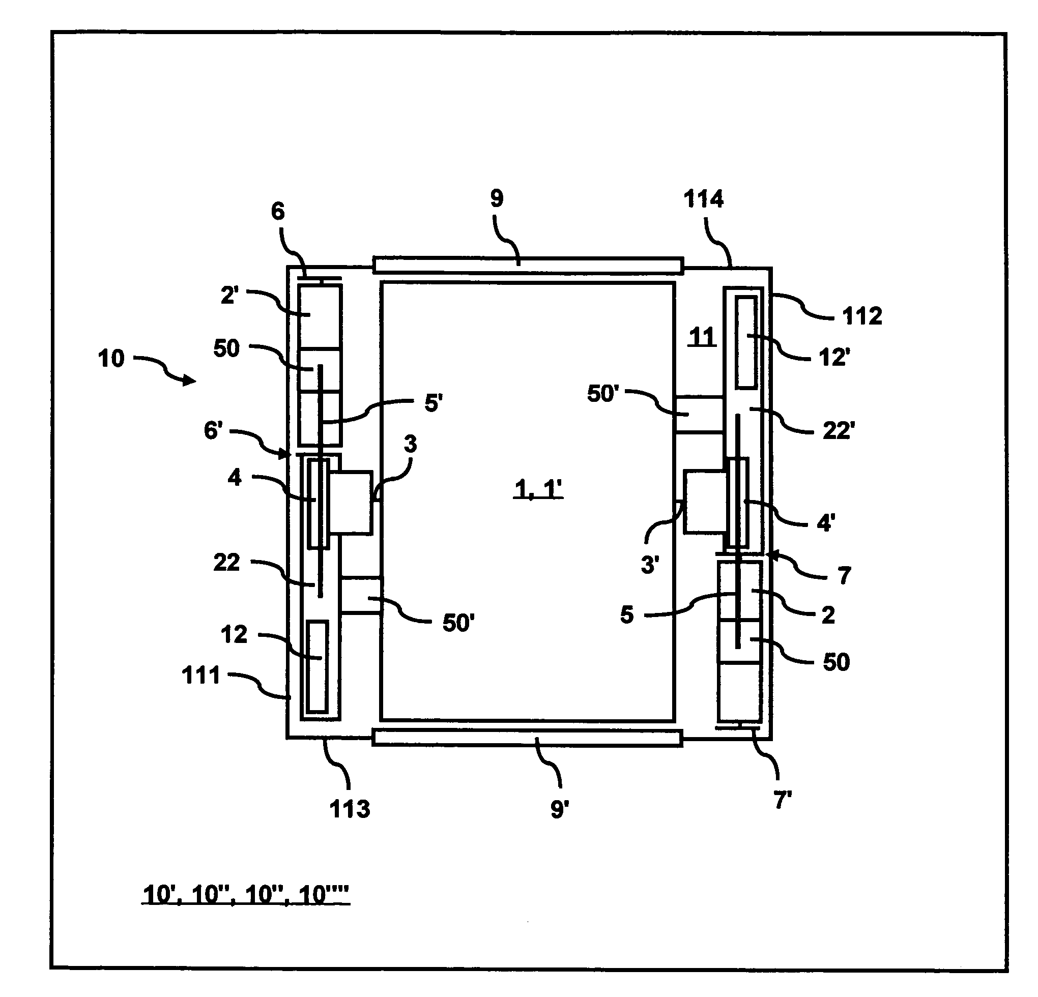
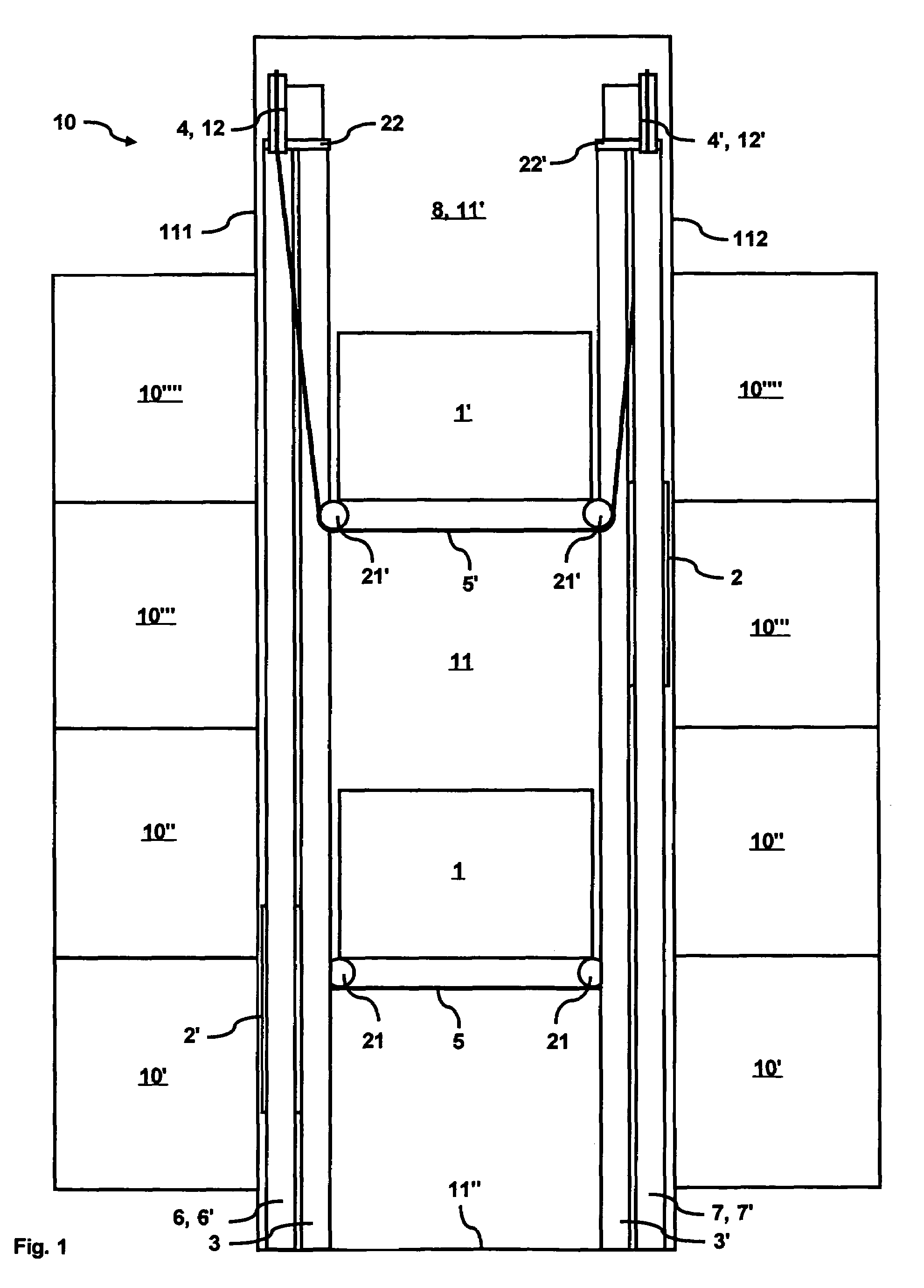
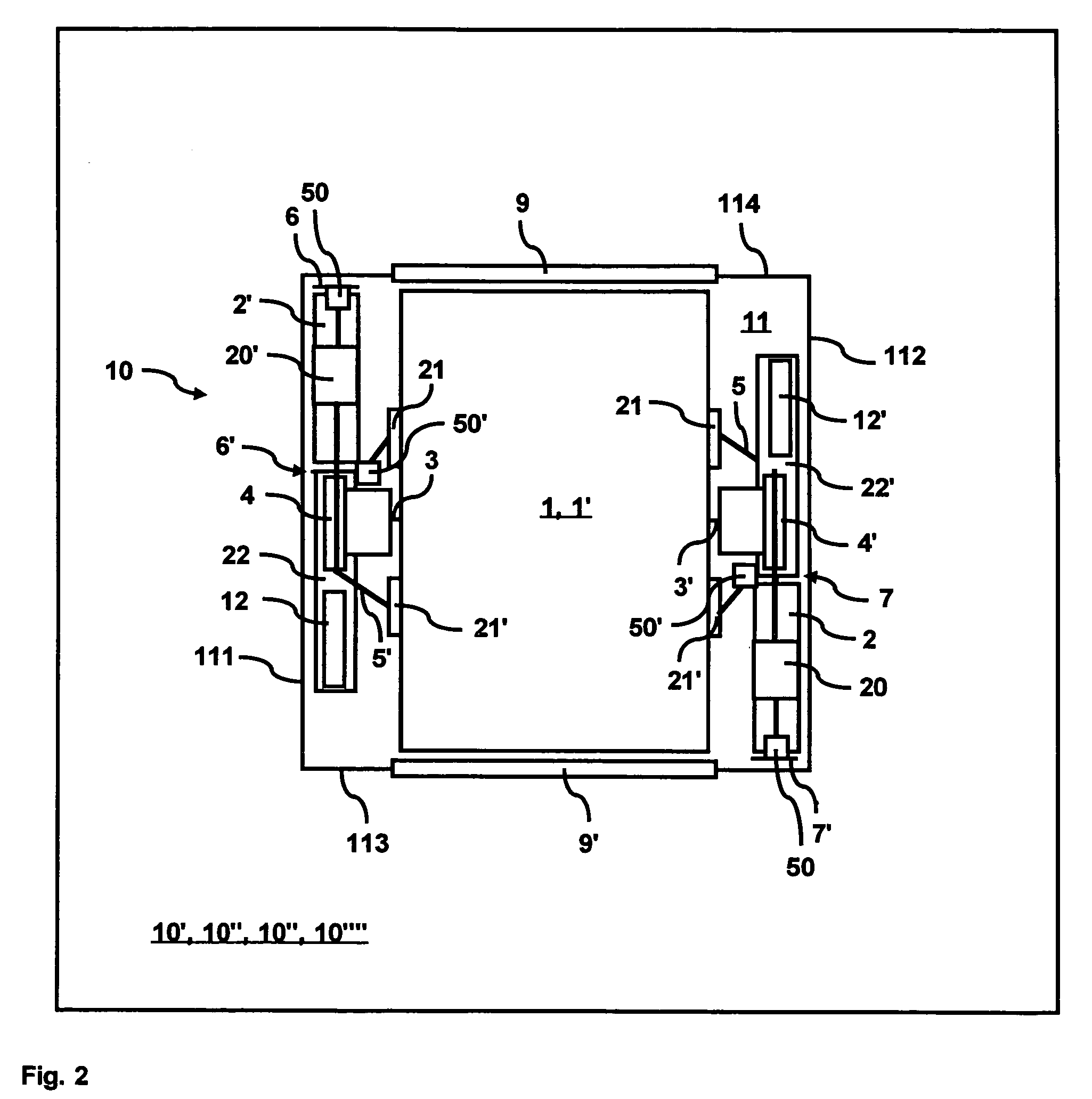
[0021]FIGS. 1 to 4 show an embodiment of an elevator installation 10 for conveying persons / goods between storeys 10, 10′, 10″, 10′″ of a building. The elevator installation 10 is advantageously installed in a shaft 11 of the building. For example, the shaft has a rectangular cross-section with a height which extends substantially completely through the building. The shaft 11 has different walls 111, 112, 113, 114, a shaft head 11′ and a shaft base 11″. The different walls 111, 112, 113, 114 are bounded by edges, which are, for example, rectangular and extend through the length of the shaft 11. The shaft can also have a different cross-sectional shape, such as a hexagon with six different walls; it can also have a circular cross-section with several different wall regions. Different wall regions are bounded by angular segments, for example a circular shaft consists of four regions each of 90° or of six wall regions each of 60°, etc. The shaft 11 can obviously also extend only partly ...


PUM


Abstract

An elevator installation for conveying persons / goods, a method for operating the elevator installation and to a method for modernizing an elevator installation. The elevator installation includes at least two cages arranged one above the other in a vertical travel direction, and a drive per cage for moving the cages. The cage and the drive are connected by way of a conveying member. A counterweight for weight compensation of each cage. At least one cage guide rail is provided for guiding the cages, and at least a pair of counterweight guide rails are provided for guiding the counterweights. The drives are arranged near different first walls in the shaft.

Description

BACKGROUND OF THE INVENTION[0001]The present invention relates to an elevator installation for conveying persons / goods, a method of operating the elevator installation and a method of modernizing an elevator installation.[0002]In the case of new installations of elevators, the desire exists for space-saving elevator installations which are simple to install. This has the consequence that the elevator installations no longer require separate engine rooms, but fit in simply conceived, standardized parallelepipedonal shafts. The costs in planning and construction of the building are thus reduced and the usable building space increases.[0003]In the case of modernizations of elevator installations, the desire exists for an increase in the conveying capacity of the elevator installations. This increase in performance, however, is to be realized with small constructional changes to the building in order to keep down the costs of modernization.[0004]U.S. Pat. No. 5,419,414 shows an elevator...

Claims


Application Information

Patent Timeline
Patent Type & Authority Patents(United States)
IPC IPC(8): B66B9/00B66B1/18B66B1/14B66B1/24B66B7/00B66B7/02B66B11/00
CPCB66B7/021B66B11/0095B66B9/00B66B19/007
Inventor DEPLAZES, ROMEOLIM, LIAN-CHOO
Owner INVENTIO AG
Why Eureka
Try Eureka