Modular adjustment device

An adjustment device and modular technology, applied in the directions of transmission parts, antenna supports/installation devices, antennas, etc., can solve the problems of complex transmission line layout and installation work that cannot be ignored, and achieve the effect of simplicity, variability and adaptability

Active Publication Date: 2018-08-31
TELEFON AB LM ERICSSON (PUBL)
View PDF12 Cites 0 Cited by
  • Summary
  • Abstract
  • Description
  • Claims
  • Application Information

AI Technical Summary

Problems solved by technology

[0009] However, the layout of such drivelines is in individual cases very complex, since several deflections may be required and the corresponding components require not negligible installation work

Method used


Image

  • Modular adjustment device
  • Modular adjustment device
  • Modular adjustment device

Examples


Embodiment Construction

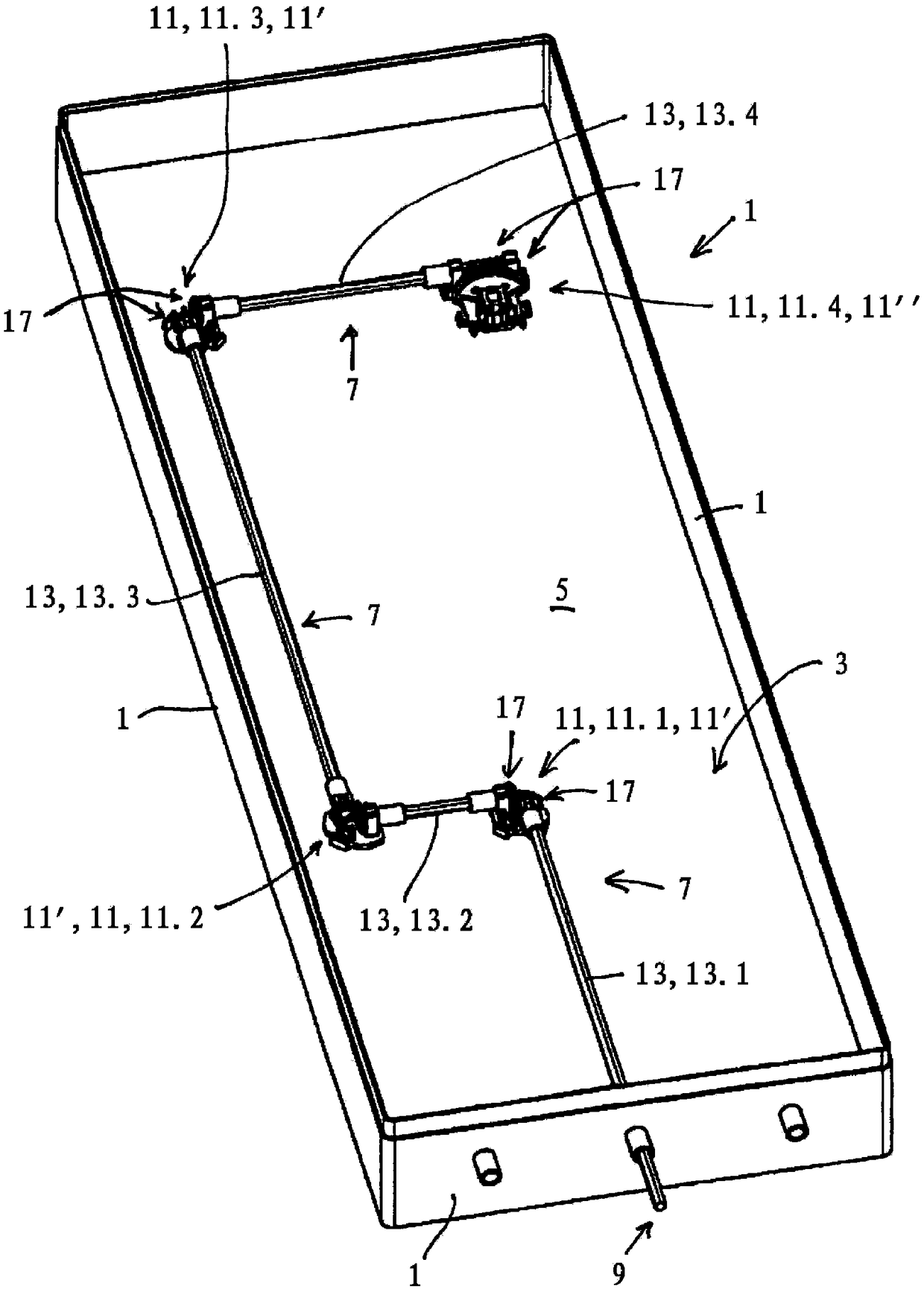
[0070] figure 1 An open housing 1 is shown by way of example in a three-dimensional illustration, which can usually be closed by means of a cover, not shown in detail, which is fitted over the housing wall 1 .

[0071] In the illustrated embodiment, a first embodiment of a modular adjustment device according to the invention for high-frequency components is shown inside the housing 3 , which is mounted on a base 5 , ie a base plate 5 . The bottom can also be a reflector of an antenna, especially a mobile communication antenna, on the opposite side of the bottom or reflector 5, for example, a common mobile communication antenna is arranged, which is figure 1 A radome, also not shown, protects and covers from environmental influences.

[0072] A printed circuit board or carrier board on which the adjustment device is mounted can also be arranged in the housing.

[0073] figure 1 A drive line 7 is shown here, starting for example from a drive side 9 located outside the housing...


PUM


Abstract

The invention relates to an improved modular adjustment device, especially for high-frequency devices, characterized in that it comprises at least one transmission basic module (113) and at least two transmission elements; said at least one transmission basic module It also includes at least one second transmission element (31) and a matching snap-in device (16); the at least one second transmission element (31) is held and fixed by the snap-fitting snap-in device (16); in order to maintain and Fixing the at least one second transmission element (31), the snap-in device (16) is configured such that the at least one second transmission element (31) is held in a defined manner in the axial direction (X) by a stop; And the first and the second transmission element (31) each have a plug-in coupling area (21), in which the shaft (13) or one of the shaft sections (13.1, 13.2, 13.3, 13.4) is connected by means of a plug-in coupling Can not be connected relative to rotation.

Description

technical field [0001] The invention relates to a modular adjustment device, in particular to a modular adjustment device for high-frequency devices. Background technique [0002] Many applications are known, especially in the field of high-frequency technology, in which an adjusting device is required to actuate actuators. [0003] It is known, for example, from WO 02 / 061877 A2 to adjust a phase shifter inside an antenna housing (radome) accordingly by means of a beam shaper, a so-called RET unit, in order to change a so-called downtilt angle. This can be done mechanically, for example by means of a RET unit which can be mounted outside the antenna housing. [0004] However, more and more components, including electronically active components such as filter components, amplifier units, etc., are arranged inside the antenna housing, so that less and less space is available. It is thus necessary, for example, to drive a phase shifter, which may be arranged inside the antenn...

Claims


Application Information

Patent Timeline
Patent Type & Authority Patents(China)
IPC IPC(8): H01Q1/12H01Q3/12H01Q3/32F16H57/021
Inventor R·亨施
Owner TELEFON AB LM ERICSSON (PUBL)
Why Eureka
Try Eureka