Device to control the functioning of a heat exchanger, heat exchanger comprising said device and corresponding control method based on the measurement of an electromagnetic field

a technology of electromagnetic field and heat exchanger, which is applied in the direction of lighting and heating apparatus, steam boiler components, corrosion prevention, etc., can solve the problems of not being very precise or reliable, affecting the operation of the heat exchanger, and indeed the presence of ice in the heat exchanger, so as to reduce the size

Inactive Publication Date: 2016-07-07
NEW TECH CONSULTANTS N T C
View PDF7 Cites 1 Cited by
  • Summary
  • Abstract
  • Description
  • Claims
  • Application Information

AI Technical Summary

Benefits of technology

[0049]Using modern technologies in this context, it is possible to achieve, according to these forms of embodiment, control devices with particularly reduced sizes and at the same time economical.

Problems solved by technology

The presence of ice in heat exchangers is indeed a particularly serious problem and these control devices can be used, in association, for example, with heaters which can be selectively activated in order to carry out, for example, an automatic defrosting of the parts of the heat exchanger affected by the formation of ice.
One disadvantage of these control devices is that they are not very precise or reliable since, detecting the overall temperature inside the exchanger, they do not allow to appreciate, for example, deposits of small amounts of ice and / or localized in specific parts of the exchanger.
One disadvantage of these control devices is that they are particularly expensive.
Some disadvantages of the devices cited above are high installation costs, difficulties in installing the sensors in proximity to the points where the ice forms, high costs of the sensors used and their limited duration over time.
Moreover, a common problem of such control devices is that they are not able to detect the presence of ice on all the parts of the heat exchanger in a uniform manner.

Method used


Image

  • Device to control the functioning of a heat exchanger, heat exchanger comprising said device and corresponding control method based on the measurement of an electromagnetic field
  • Device to control the functioning of a heat exchanger, heat exchanger comprising said device and corresponding control method based on the measurement of an electromagnetic field
  • Device to control the functioning of a heat exchanger, heat exchanger comprising said device and corresponding control method based on the measurement of an electromagnetic field

Examples


Embodiment Construction

[0060]We shall now refer in detail to the various forms of embodiment of the present invention, of which one or more examples are shown in the attached drawing. Each example is supplied by way of illustration of the invention and shall not be understood as a limitation thereof. For example, the characteristics shown or described insomuch as they are part of one form of embodiment can be adopted on, or in association with, other forms of embodiment to produce another form of embodiment. It is understood that the present invention shall include all such modifications and variants.

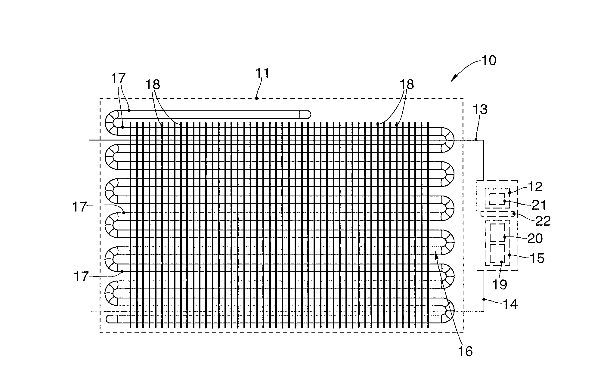
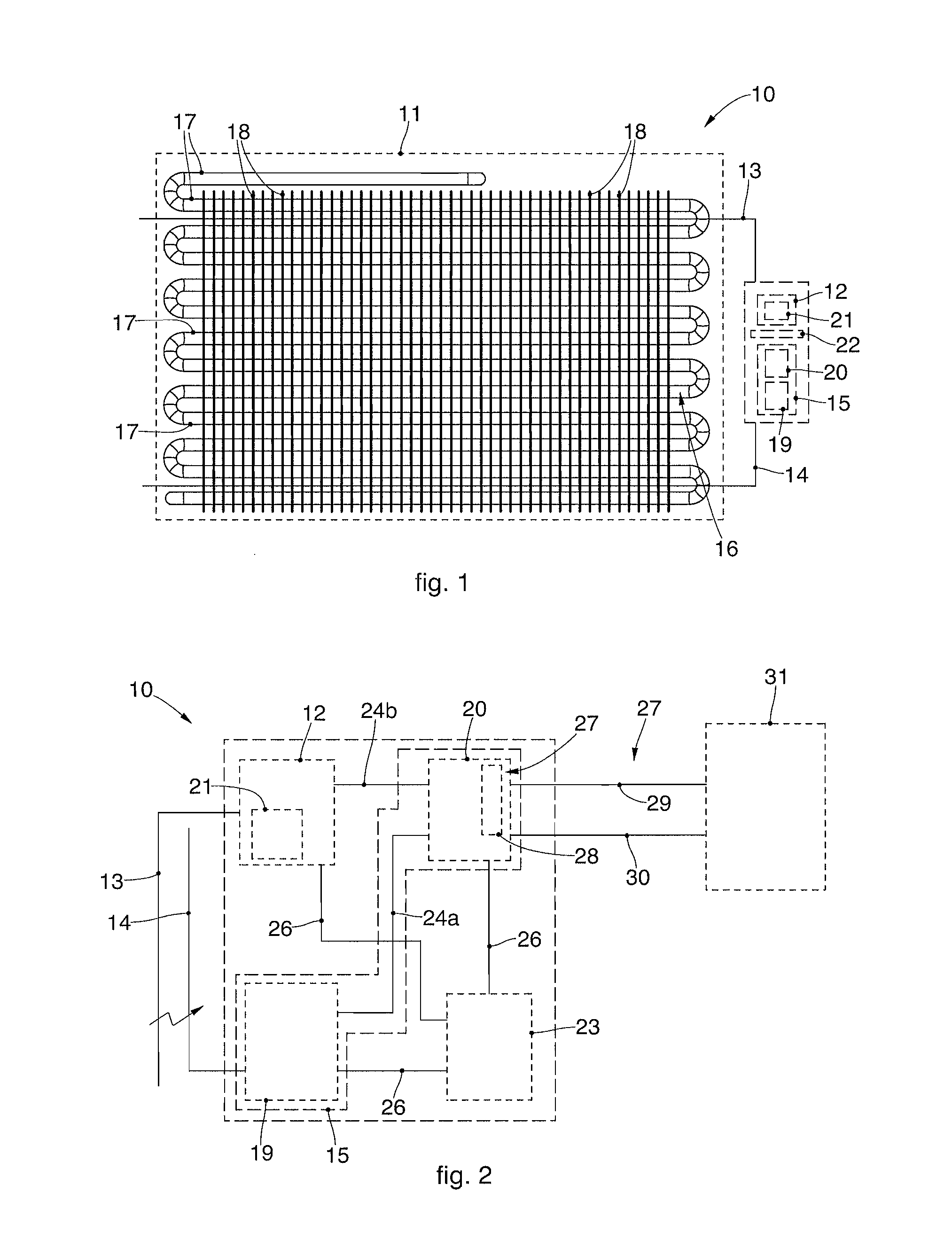
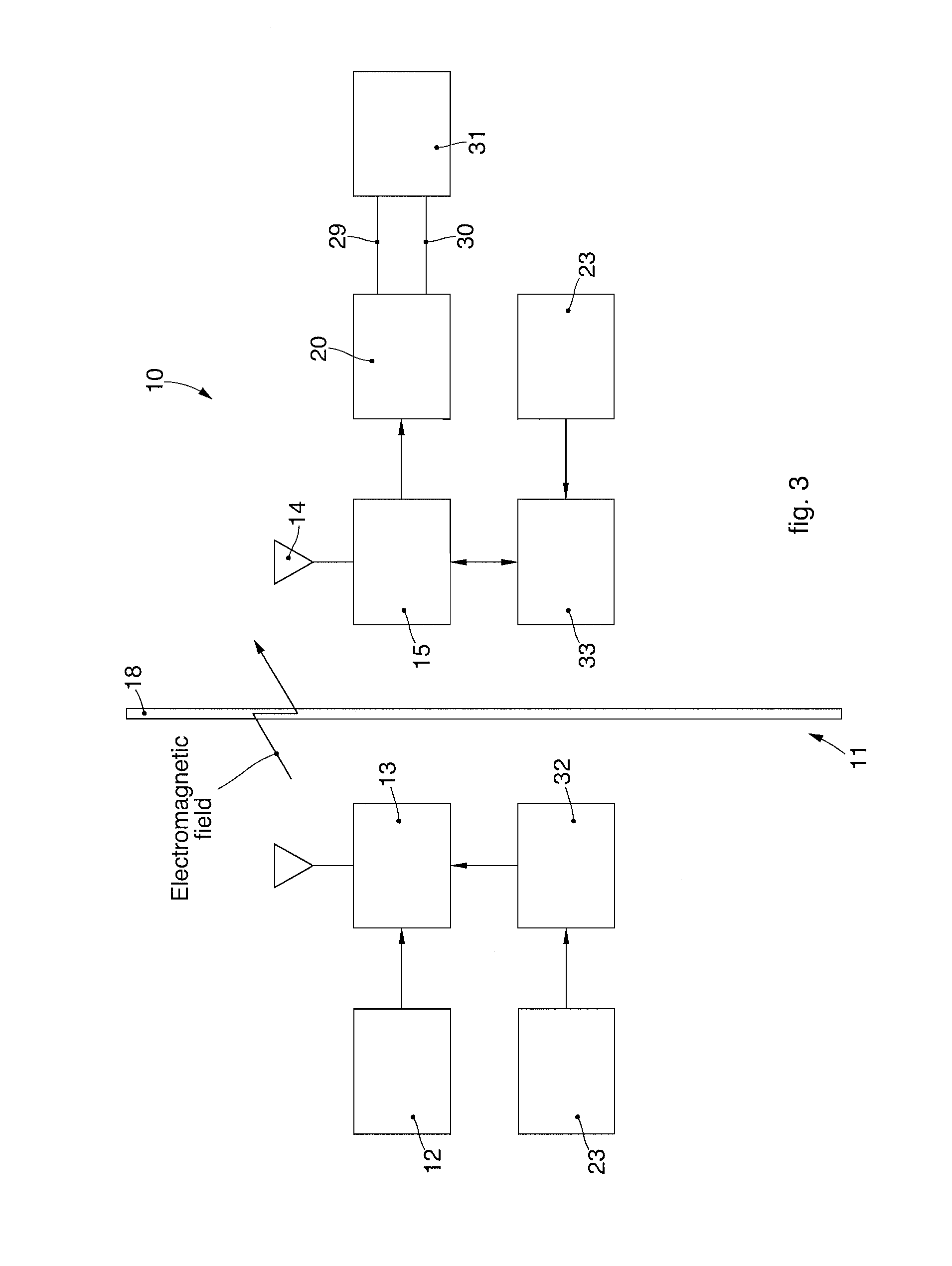
[0061]FIG. 1 is used to describe forms of embodiment of a device 10 to control the functioning of a heat exchanger 11, comprised, by way of example, in a plant or an apparatus for cooling and / or conditioning.

[0062]The control device 10 comprises an electric generator 12 suitable to generate an electric quantity, such as a current and / or a tension, with suitable modulation and encoding method, and a high-frequ...


PUM


Abstract

A device to control the functioning of a heat exchanger comprises an electric generator, suitable to generate an electromagnetic field, at least an emission element, connected to the electric generator and associable with the heat exchanger, to generate in the latter an electromagnetic field, at least a detection element, configured to detect a value of the electromagnetic field with respect to the value generated by the electromagnetic field, and a detector, connected to the detection element with an appropriate de-modulation and de-coding method to determine functioning conditions of the heat exchanger.

Description

FIELD OF THE INVENTION[0001]The present invention concerns a device to control the functioning of a heat exchanger, comprised by way of example in a plant or an apparatus, for cooling and / or conditioning.[0002]The present invention also concerns the heat exchanger that includes the control device according to the invention, and the corresponding method of controlling the functioning of a heat exchanger based on the measurement of an electromagnetic field.BACKGROUND OF THE INVENTION[0003]Various control devices are known, for controlling the functioning of heat exchangers and in particular those that allow to detect the presence of ice or frost on parts of the exchanger, in particular on the fins.[0004]The presence of ice in heat exchangers is indeed a particularly serious problem and these control devices can be used, in association, for example, with heaters which can be selectively activated in order to carry out, for example, an automatic defrosting of the parts of the heat excha...

Claims


Application Information

Patent Timeline
Patent Type & Authority Applications(United States)
IPC IPC(8): F28F27/00
CPCF28F2200/005F28F27/00F28F19/006F25B2700/11
Inventor MONACO, FRANK ANTHONY
Owner NEW TECH CONSULTANTS N T C
Why Eureka
Try Eureka