
Belt lock with status detector

a technology of status detector and belt lock, which is applied in the field of belt locks, can solve the problems of complex and expensive subsequent installation of hall sensors, complicated structure or installation, and high cost of hall sensors, and achieve the effect of simplifying mounting and simplifying installation

Inactive Publication Date: 2013-10-01
POLYCONTACT
View PDF4 Cites 0 Cited by
  • Summary
  • Abstract
  • Description
  • Claims
  • Application Information

AI Technical Summary

Benefits of technology

The solution enables reliable detection of the belt lock's state without external interference, ensuring accurate locking and unlocking status, and simplifies installation and maintenance, while maintaining a compact design suitable for retrofitting existing systems.

Problems solved by technology

A disadvantage in the belt lock according to EP-A-0 861 763 is that the Hall sensor must be positioned very carefully with reference to the locking element or the ejector.
Subsequent installation of the Hall sensor is therefore relatively complex and expensive.
This further complicates the structure or the installation.
This can make it difficult to detect different states, for example, the belt lock locked or unlocked.
Vibrations of the locking body and of the ejector during locking and unlocking of the seat belt can cause demagnetization of the permanent magnet with time.
This can ultimately lead to the Hall sensor becoming ineffective and the status changes of the belt lock no longer being able to be reliably detected.
The known belt locks can have a compact design that therefore can seriously limit the available space within the belt lock.
This makes it difficult to arrange sensor components within the belt lock housing, especially in the vicinity of a component that changes its location from one end position into the other end position when the belt lock is actuated.
If shields are also to be attached, the engineer is generally faced with an essentially insoluble problem because the dimensions of the belt lock housing are not to be changed.

Method used


Image

  • Belt lock with status detector
  • Belt lock with status detector
  • Belt lock with status detector

Examples


Embodiment Construction

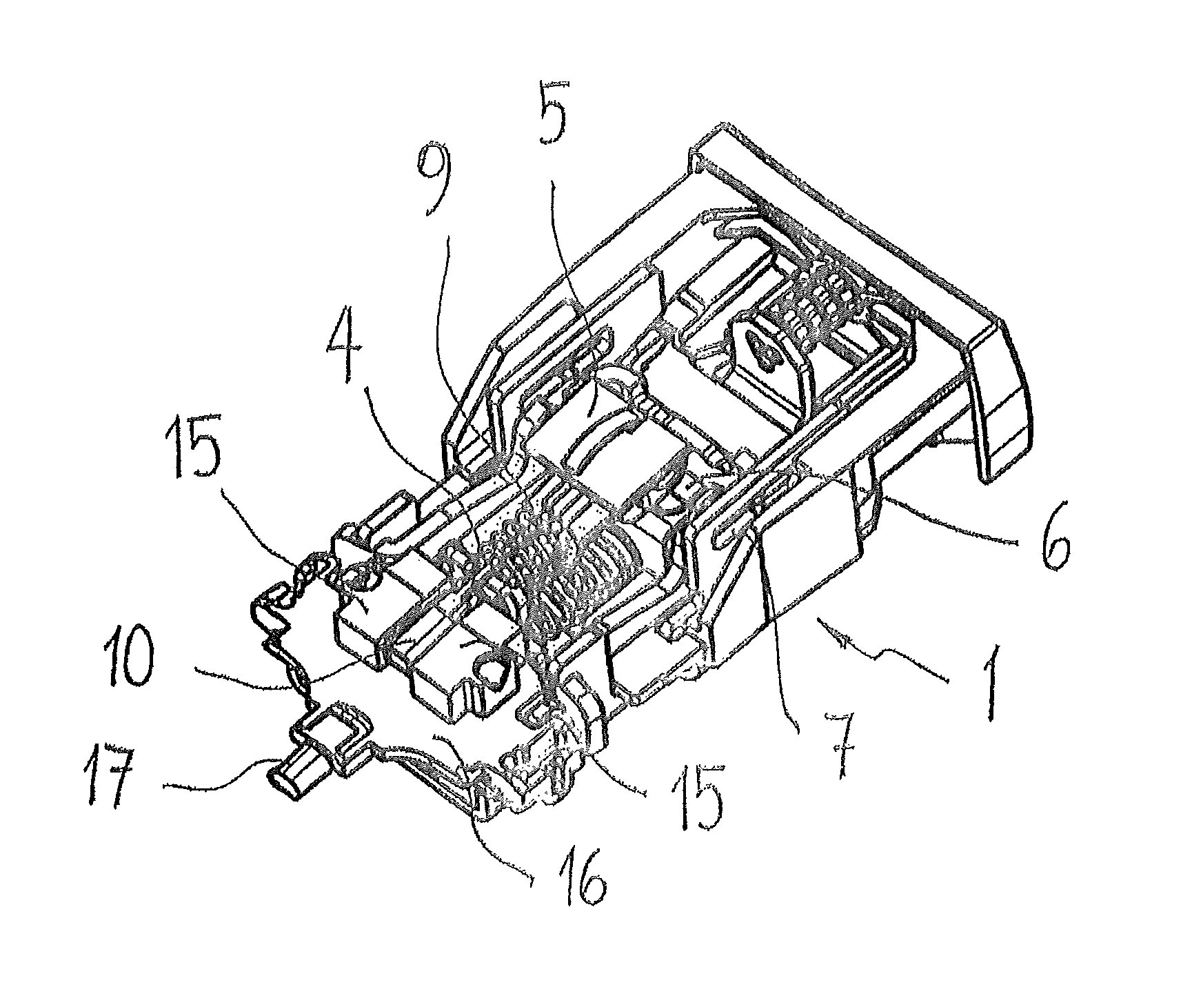
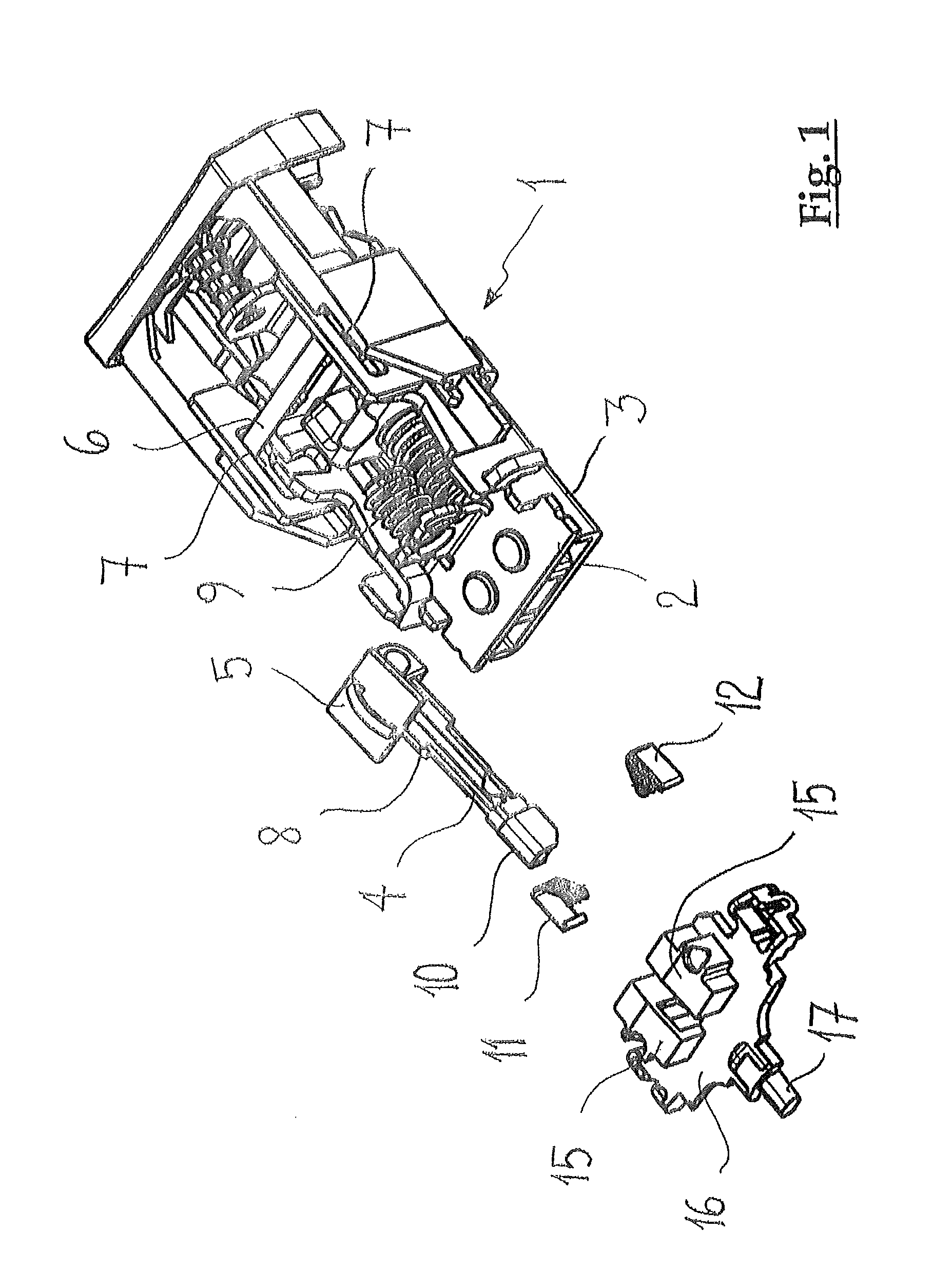
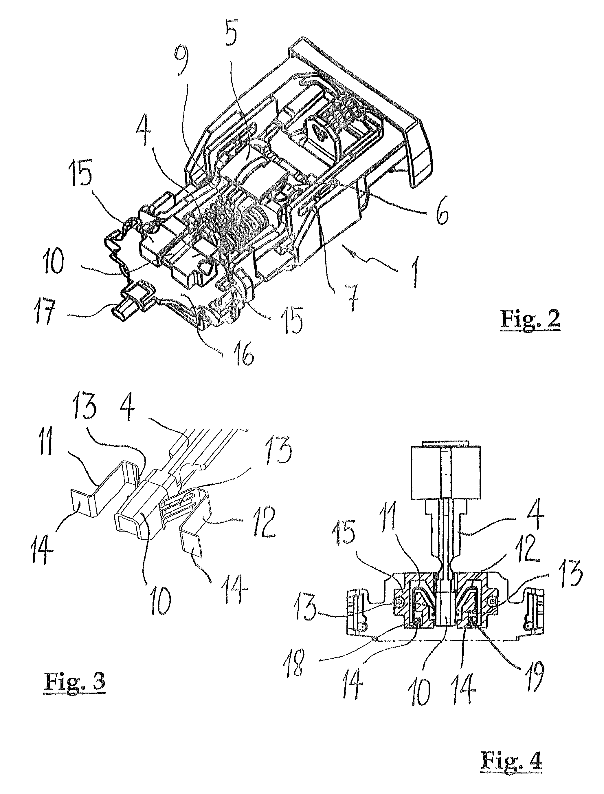
[0023]The belt lock shown in FIG. 1 in a partially exploded perspective view and in FIG. 2 in the assembled state corresponds largely to the belt lock shown in EP-1 025 774 B1 using FIGS. 1-6, the entire contents of which are hereby incorporated by reference. The following description of the disclosure is therefore limited to the components of the belt lock that are important to the understanding of the disclosure.

[0024]FIGS. 1 and 2 show the belt lock in each case without the belt lock housing. For example, the belt lock housing includes two housing shells that can be screwed to one another or can be bonded to one another in any suitable manner. A fastener frame of the belt lock is provided with the reference number 1 as a whole. The fastener frame 1 is composed of an upper and a lower plate 2, 3 that can be connected to one another by connecting pins. Between the upper and lower plates 2, 3, a guide channel remains open into which the metallic clip of the seat belt can be inserted...


PUM


Abstract

A belt lock for a seat belt that has a locking mechanism that is arranged in a belt lock housing. The locking mechanism includes a component that changes location from a first end position into a second end position when the locking mechanism is actuated, and in doing so interacts with a status detector. The status detector is designed as an electrical switching system. The component that changes location is a mandrel that can be moved axially when the locking mechanism is actuated and that is provided with an electrically conductive contact region and forms a component of the electrical switching system.

Description

RELATED APPLICATIONS[0001]This application claims priority under 35 U.S.C. §119 to Swiss Patent Application No. 01514 / 09 filed in Switzerland on Oct. 1, 2009, the entire content of which is hereby incorporated by reference in its entirety.FIELD[0002]The disclosure relates to a belt lock for a seat belt, for example in an automobile, with a status detector.BACKGROUND INFORMATION[0003]In technical applications, such as, for example, automobile construction and the like, it can be necessary to quickly and reliably detect the location of a component that can be moved into two end positions relative to a stationary part, using measurement technology. In the case of a belt lock of an automobile, it can be checked, for example, whether a passenger is belted or not. Knowledge of the state of the belt lock is useful to notify a passenger by a signal to put on and fasten the seat belts. Since the introduction of airbags, information about the closed state of the seat belts has also been usefu...

Claims


Application Information

Patent Timeline
Patent Type & Authority Patents(United States)
IPC IPC(8): B60Q1/00E05B45/06A41F1/00
CPCB60R22/48A44B11/2569Y10T24/45Y10T24/45623Y10T24/45079B60R2022/4816
Inventor LANTER, JOSHUALOMBRISER, CLAU
Owner POLYCONTACT
Learn More