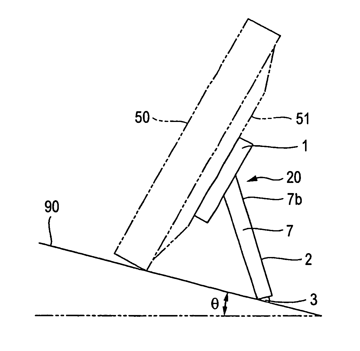
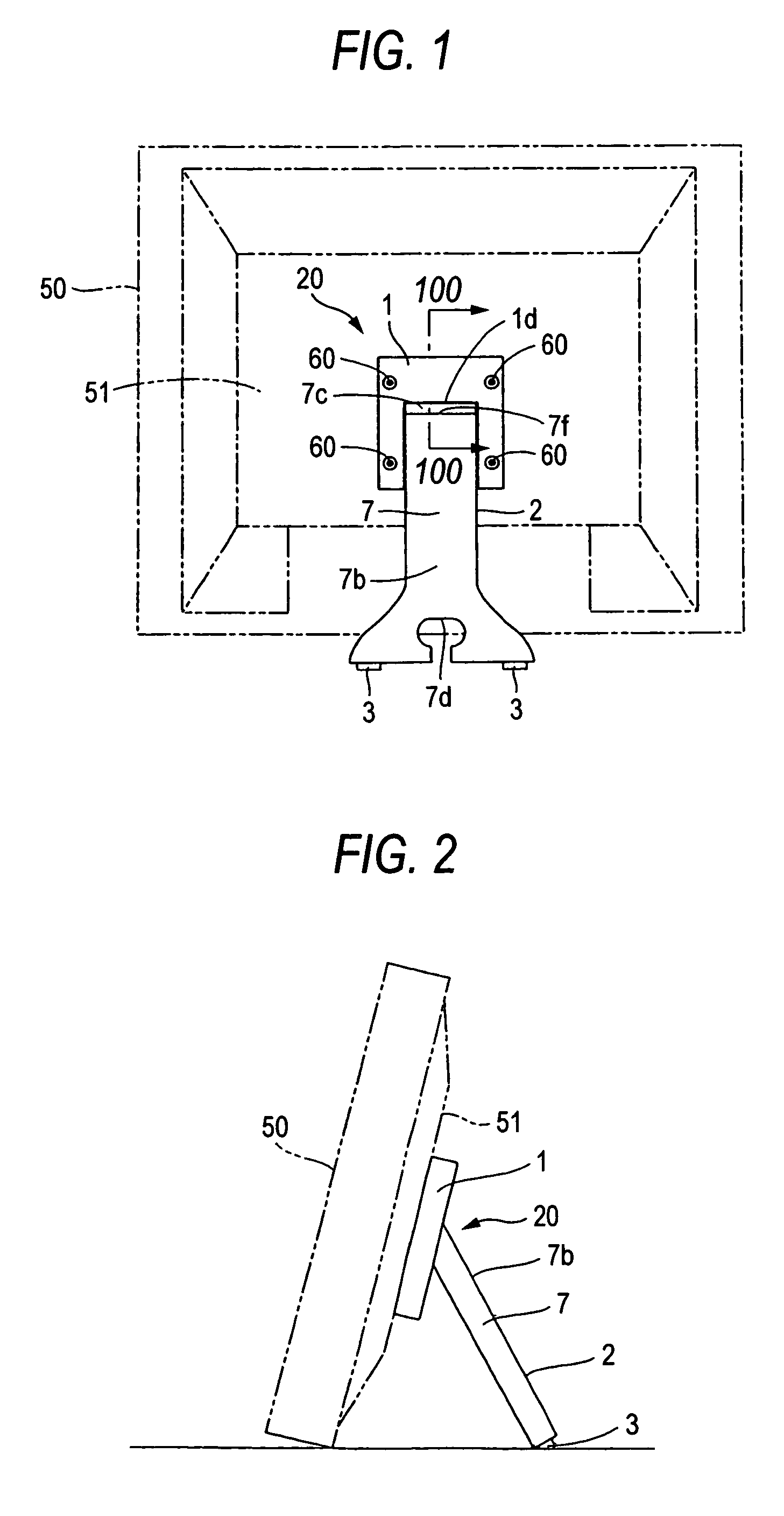
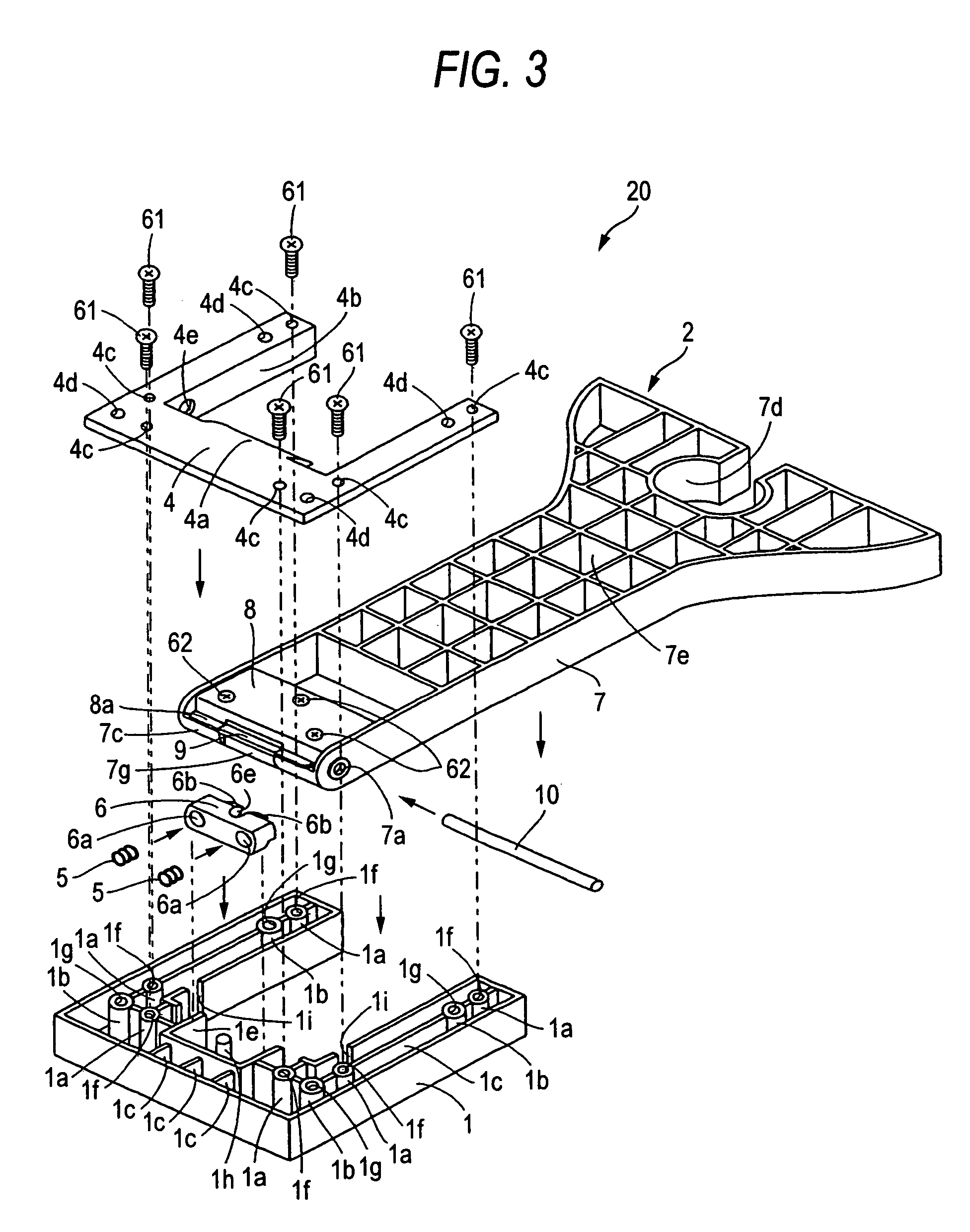
[0019]The support structure for liquid crystal television receiver according to this first aspect of the invention is provided as mentioned above with a cross-sectionally triangular projection including the first inclined surface and the second inclined surface, which are engaged with the support member as the inclined surfaces press the support member, on the pressure member. Therefore, when the support member is turned from a closed position toward an opened position, the support member engages with the first inclined surface of the pressure member. Before the support member gets over the first inclined surface, the support member is pressed by the first inclined surface of the pressure member, which is urged by the compression coiled spring toward the support member, the support member can be returned to the pivotal position in which the support member is closed, even though the support member is turned at a predetermined angle. When the support member is turned from a closed state to an opened state, the support member is pressed by the second inclined surface of the pressure member urged toward the support member by the compression coiled springs after the support member gets over the first inclined surface and reaches the same inclined surface. This enables the support member to be automatically placed, in a pivotal position (supporting position) in which the support member is in an opened state, owing to the pressing force of the second inclined surface. As a result, the liquid crystal television receiver can be supported stably in the supporting position. This can prevent the support member from being held in an intermediate pivotal position other than the pivotal position in which the support member is in a closed state or in an opened state. As a result, the liquid crystal television receiver can be supported stably in a supporting position.
[0020]Since the compression coiled springs having a large force urging the support member toward the pressure member are used in the first aspect of the invention, the support member can be pressed by such a level of force that is larger than that in the case where the pressing force of an elastic metal member is used. Even when a large force of not lower than a predetermined level by which the support member is turned in the support member closing direction is imparted thereon in the supporting position in which the support member is in an opened state, the turning of the support member in the opened state to the support member closing position can be suppressed more effectively than in a case where the support member is pressed by an elastic metal member, such as a leaf spring. Fixing to the base member the holding member including an inhibition portion for inhibiting the turning of the support member to a position beyond the supporting position enables the turning of the support member beyond the supporting position to be suppressed owing to the inhibition portion of the holding member even when the support member is nearly turned to a position beyond the supporting position. Since the recess engaged with the first inclined surface of the pressure member when the support member is in an opened state is provided on the support member, the first inclined surface of the pressure member urged in the supporting position by the compression coiled spring can be engaged with the recess of the support member, so that the support member can be retained in the opened condition (supporting position) more stably. The boss portions are formed in the base member, and a recess in some of the boss portions of the base member which are opposed to the boss portions of the base member are formed in the pressure member. When the pressure member and compression coiled springs which are adapted to urge the pressure member toward the support member are provided on the base member, the boss portions of the base member can thereby be engaged with the groove of the pressure member. Therefore, even when the compression coiled springs and pressure member are provided so that the springs and pressure member are bent and pressed toward the support member respectively, the pressure member can be set with the compression coiled springs left bent owing to the boss portions of the base member. This enables the pressure member and compression coiled springs to be combined easily with the base member. Since the end portion pressed by the pressure member of the support member is provided with the metal reinforcement member. Therefore, even when the portion of the support member which presses the pressure member is pushed by the pressure member with a force not lower than a predetermined level, the breakage of the support member can be suppressed by the metal reinforcement member.
[0022]In the second aspect of the present invention for a display device, the pressure member is provided as described above with a cross-sectionally triangular projection having a first inclined surface and a second inclined surface which engage with the support member while pressing the same. Owing to this structure, before the support member engages with and gets over the first inclined surface while the support member is turned from the closed state toward the opened state, the support member is pressed by the first inclined surface of the pressure member urged toward the support member by the compression coiled springs even though the support member is turned at a predetermined angle, so that the support member can be returned to the pivotal position in which the support member is in a closed state. When the support member is turned from the closed state toward an opened state, the support member is pressed by the second inclined surface of the pressure member urged toward the support member by the compression coiled sprins after the support member gets over the first inclined surface and reaches the second inclined surface, so that the support member can be automatically placed in the pivotal position (supporting position) in which the support member is in the opened state owing to the pressing force of the second inclined surface. Owing to this structure, the retaining of the support member in an intermediate position other than the position in which the support member is in a closed state or opened state can be restrained. As a result, the display device can be supported in a supporting position stably. Since the compression coiled spring of a large urging force urging the pressure member toward the support member is provided, the support member can be pressed with a force larger than that imparted to a support member using an elastic metal member, such as a leaf spring. Therefore, even when a force the level of which is not lower than a predetermined level, at which the support member is turned in the closing direction, is imparted to the support member in the supporting position in which the support member is in an opened state, the turning of the support member from the opened state can be restrained more effectively than in a case where the support member is pressed by an elastic metal member, such as a leaf spring. Since the holding member including a inhibition portion for inhibiting the turning of the support member to a position beyond the supporting position is fixed to the base member, the turning of the support member beyond the supporting position can be restrained by the inhibition portion of the holding member even when the support member is nearly turned to a position beyond the supporting position.
[0024]In the support structure for a display device according to the above-described second aspect of the invention, the base member preferably includes boss portions, and the pressure member is provided with a groove at the portion thereof which is opposed to the boss portions of the base member. When the support structure is thus formed, the boss portions of the base member and the groove of the pressure member can be engaged with each other when the pressure member and the compression coiled springs for urging the pressure member toward the support member are provided on the base member. Even when the compression coiled springs and pressure member are provided so that the coiled springs and pressure member are in a bent state and in a pressing state in which the pressure member is pressed thereby toward the support member respectively, the pressure member can be provided with the compression coiled springs left in a bent state owing to the boss portions of the base member. This enables the pressure member and compression coiled springs to be combined easily with the base member.


