Joint aspirate facilitating device

a technology of aspiration device and joint, which is applied in the field of orthopaedic devices, can solve the problems of increasing costs, difficulty in performing knee aspiration, and lack of prior art devices providing adequate functionality for facilitating joint aspiration procedures, etc., and achieves the effect of increasing the capacity of a medical practitioner, increasing the size and pressure of the fluid sac, and increasing the volume and pressure of the joint fluid

Active Publication Date: 2008-12-23
NAT JEWISH MEDICAL & RES CENT
View PDF104 Cites 39 Cited by
  • Summary
  • Abstract
  • Description
  • Claims
  • Application Information

AI Technical Summary

Benefits of technology

[0006]In order to overcome the various disadvantages inherent in conducting joint aspiration procedures, and to overcome the failure of the prior art to address such needs in the medical field, a joint aspirate-facilitating device is provided to enhance the capability of a medical practitioner to successfully perform a joint aspiration procedure. The device is made of a flexible, cloth-like material that incorporates an inflatable bladder. The bladder is specially sized and positioned to place pressure on specified regions of the joint to thereby displace distended joint fluid into a targeted location. The volume and pressure of the joint fluid is increased at the targeted location thereby increasing the size and pressure of the fluid sac where the aspirating needle can be placed to successfully aspirate the joint.
[0007]In a first embodiment, the joint aspirate-facilitating device resembles a traditional knee brace, but adopts unique structural features to facilitate a successful aspiration procedure. In this embodiment, the inflatable bladder is located to displace knee joint fluid from the contra lateral, superior, inferior and posterior joint regions towards a targeted location. An access opening is formed in the device at the targeted location. The aspirating needle penetrates the joint at the access opening, and the increased volume and pressure of the fluid located at the opening greatly enhances the ability of the practitioner to successfully penetrate the fluid sac. The access opening is preferably located either on the medial or lateral side of the knee joint, and is oriented to allow the medical practitioner to specifically access the suprapatellar bursae from the medial or lateral side.
[0008]The device of the present invention preferably incorporates a lightweight, washable fabric with a removable inflatable bladder controlled by an external, hand-operated pump to selectively pressurize the bladder. A pressure release element is provided to release or adjust pressure. A pressure gauge may be incorporated with the hand pump to allow the practitioner to monitor the amount of applied pressure. An internal pocket may be formed on an inner side of the device placed against the patient. The bladder is secured in this pocket during use. The bladder when deflated can be easily removed from the pocket to allow the device to be washed or otherwise serviced. A closure element, such as hook and pile material, may be used to secure both the internal bladder to the pocket as well as to tightly secure the device around the joint.
[0009]The device of the present invention can incorporate a disposable sterile field dressing to minimize risk of inadvertent inoculation of bacteria into the sterile cavity of the joint. In yet another embodiment of the invention, the access opening formed in the device can be used in a non-interventional procedure such as an ultrasound procedure to visualize the tissue located at the access opening. The device may include sleeves formed on the outer surface thereof to hold an ultrasound probe that is positioned at the access opening.
[0010]In one preferred embodiment, a single access opening can be provided at either the medial or lateral locations for aspirating a knee joint. In another embodiment, a pair of access openings can be provided at the medial and lateral locations, and depending whether a medial or lateral approach is taken, the unused access opening is blocked with a plug thereby encouraging fluid displacement from the opposite side of the joint.
[0012]With the joint aspiration device of the present invention, the increased volume and pressure of the fluid to be aspirated increases the effective size of the targeted area, thereby reducing the chance that the aspirating needle will strike bone or will strike unintended tissue such as nerves or tendons. The device can be made in various sizes to accommodate joint sizes encountered with adults, children, or obese patients.

Problems solved by technology

Accordingly, increased costs may be incurred because a medical specialist is typically required to conduct the procedure.
Even with experienced specialists, knee aspirations can be difficult to perform because there is a very small area in which the aspirating needle can be inserted in the joint without striking pain-sensitive structures including bone or ligaments.
With respect to the prior art discussed above, while a number of inflatable knee brace configurations are known, none of the prior art devices provide adequate functionality for facilitating a joint aspiration procedure.

Method used


Image

  • Joint aspirate facilitating device
  • Joint aspirate facilitating device
  • Joint aspirate facilitating device

Examples


Embodiment Construction

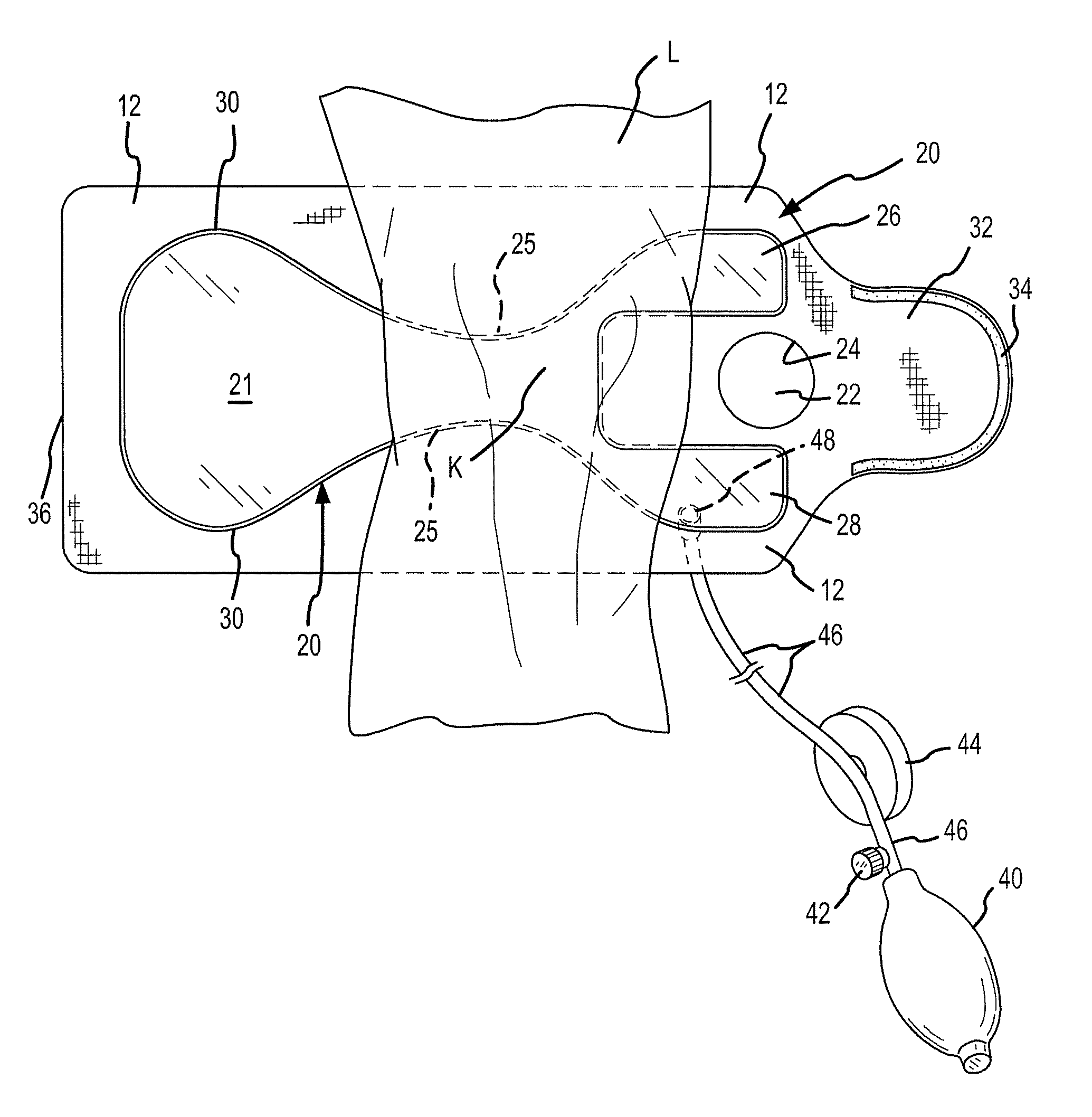
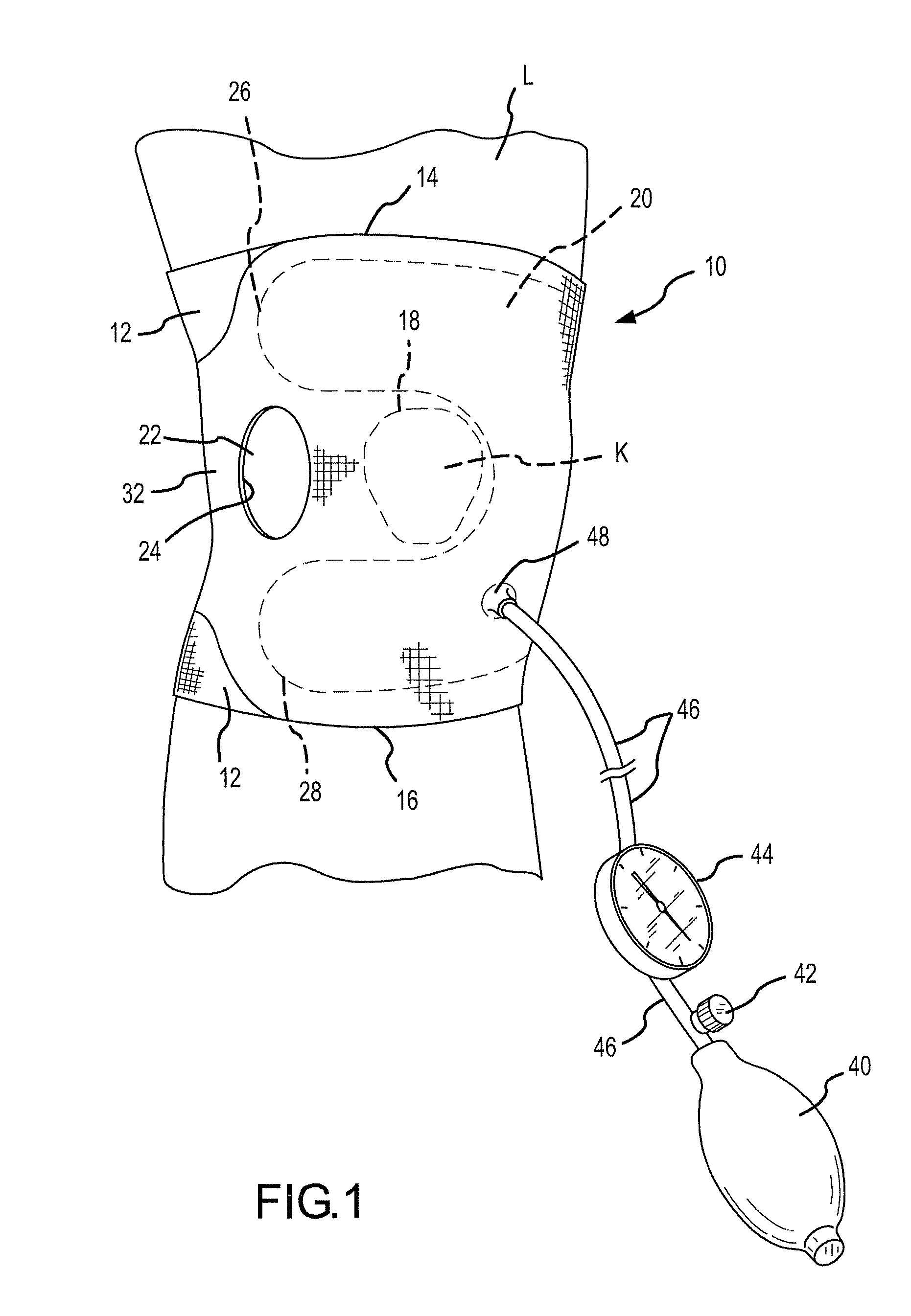
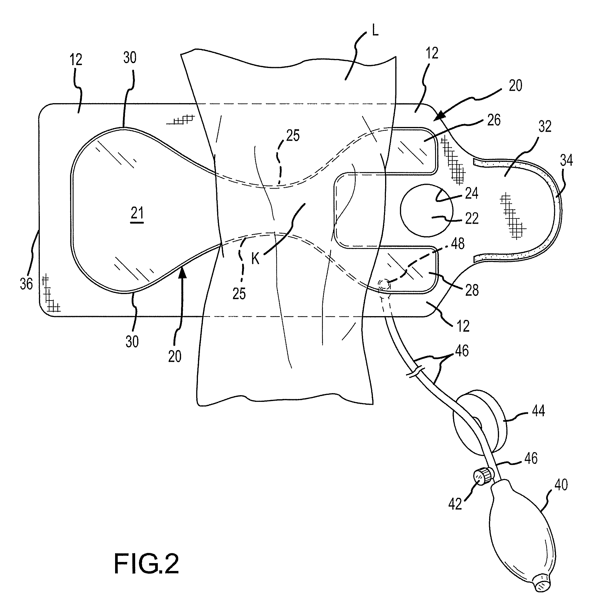
[0025]FIGS. 1 and 2 illustrate a first embodiment of the joint aspirating device of the present invention. In this embodiment, the device is used for facilitating aspiration of the knee joint. The aspirating device 10 includes a main panel or body 12 made of a flexible material that is wrapped around the joint. A bladder 20 is used to selectively apply pressure to the joint in order to cause joint fluid displacement to a targeted location. Preferably, the material is flexible but not elastomeric / elastic, since it is desirable to immobilize the joint so that the inflatable bladder 20 precisely displaces the joint fluid without deformation or stretching of the main panel. As shown, the main panel 12 is orientated with respect to the leg L of the patient so that upper and lower edges 14 and 16 extend transversely. One longitudinal side of the main panel 12 is defined by edge 36. The opposite longitudinal side is defined by flap 32 that is used to secure the device to the patient. As sh...


PUM


Abstract

A joint aspirate-facilitating device is provided including a flexible main panel that is secured to the joint to be aspirated. An inflatable bladder is secured to the main panel and is placed in contact with the soft tissues overlying and surrounding the joint space. The bladder is used to apply pressure to selected areas of the joint to compress the fluid sacs in the joint. An access opening is formed in the main panel designating the location where joint fluid is to be aspirated. The joint fluid is directed to flow to the area of the joint exposed at the access opening based on the shape of the bladder that compresses surrounding areas of the fluid sacs. A conventional hand pump may pressurize the bladder or the bladder may be filled with a viscous gel material to generate pressure. Multiple access openings may be formed on the main panel designating locations where aspiration is to be conducted. For multiple access openings, plugs may be used to fill those openings where aspiration is not conducted, thereby maximizing joint fluid flow only to the selected location where aspiration is to be conducted. An ultrasound probe may be attached and incorporated into the device to confirm joint fluid displacement into the targeted location prior to need aspiration. A disposable molded sterile dressing may applied to the access opening to reduce the risk of infections. The device can be used on any joint of the body, and the particular shape of the main panel and bladder accommodates maximum joint fluid flow to the point where aspiration is desired.

Description

FIELD OF THE INVENTION[0001]The present invention relates to orthopedic devices used to support a joint, and more particularly, to an orthopedic appliance for facilitating aspiration of joint fluid in the knee or other joints such as the ankle or elbow.BACKGROUND OF THE INVENTION[0002]There are a number of orthopedic appliances that are used to support or immobilize various body parts. With respect to stabilizing or immobilizing the knee joint because of an injury, some of these orthopedic appliances include the use of inflatable air bladders for intermittently supporting and / or releasing support on the knee. One example of an inflatable knee brace includes U.S. Pat. No. 3,983,056, which describes inflatable tubes stitched into a fabric support extending vertically over a portion of the support. U.S. Pat. No. 4,430,042 describes a pillow type device strapped to the leg of a patient and then inflated. U.S. Pat. No. 4,872,448 discloses a U-shaped inflatable bladder placed over the pat...

Claims


Application Information

Patent Timeline
Patent Type & Authority Patents(United States)
IPC IPC(8): A61F5/00
CPCA61F5/0104A61F5/012
Inventor MEEHAN, RICHARD
Owner NAT JEWISH MEDICAL & RES CENT
Why Eureka
Try Eureka