Microwave bandstop filter for an output multiplexer

a multi-channel, filter technology, applied in the direction of delay lines, electrical devices, coupling devices, etc., can solve the problems of inability to achieve satisfactory filtering and inability to meet high-power applications, and achieve the effect of effective filtering, simple and easy to mak

Inactive Publication Date: 2008-12-23
EUROPEAN SPACE AGENCY
View PDF14 Cites 3 Cited by
  • Summary
  • Abstract
  • Description
  • Claims
  • Application Information

AI Technical Summary

Benefits of technology

[0006]An object of the present invention is to make it possible to achieve effective filtering over a broad band at high frequencies even in high power applications, and to do using a device that presents a structure that is particularly simple and easy to make. By way of example, the invention makes it possible to obtain attenuation of at least 25 decibels (dB) over a band having a width of several gigahertz at frequencies greater than 15 GHz, while making use solely of a passive structure in the form of a waveguide.
[0020]the mean transverse dimensions of the waveguide section constituting said or each bandstop filter and the maximum amplitude of the longitudinal variation of its cross-section are such that they enable power of at least 0.5 kW to be conveyed in the microwave region of the spectrum without any danger of electron avalanche discharges occurring in a vacuum; and

Problems solved by technology

However, filters known in the prior art do not enable satisfactory filtering to be obtained while simultaneously conveying high power.
The magnitudes of these interfering passbands increase with increasing spacing or gap between the walls of the waveguide in the electric field direction of the waves being conveyed, which leads to operation of multimode type: consequently, in order to be effective in eliminating the undesirable frequencies, it is necessary to use filters with a small gap, but that is not possible in high power applications (power of kilowatt or greater order), in particular when the filter is to be used in a vacuum, because of the risk of electron avalanche discharges (“multipaction”).

Method used


Image

  • Microwave bandstop filter for an output multiplexer
  • Microwave bandstop filter for an output multiplexer
  • Microwave bandstop filter for an output multiplexer

Examples


Embodiment Construction

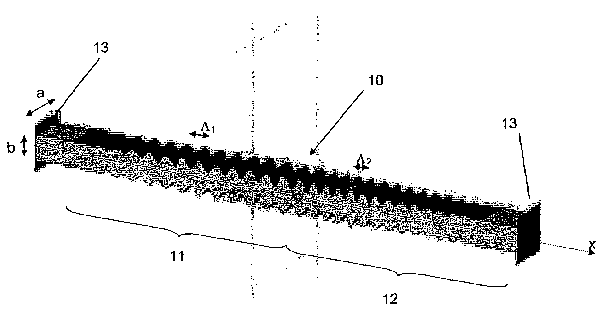
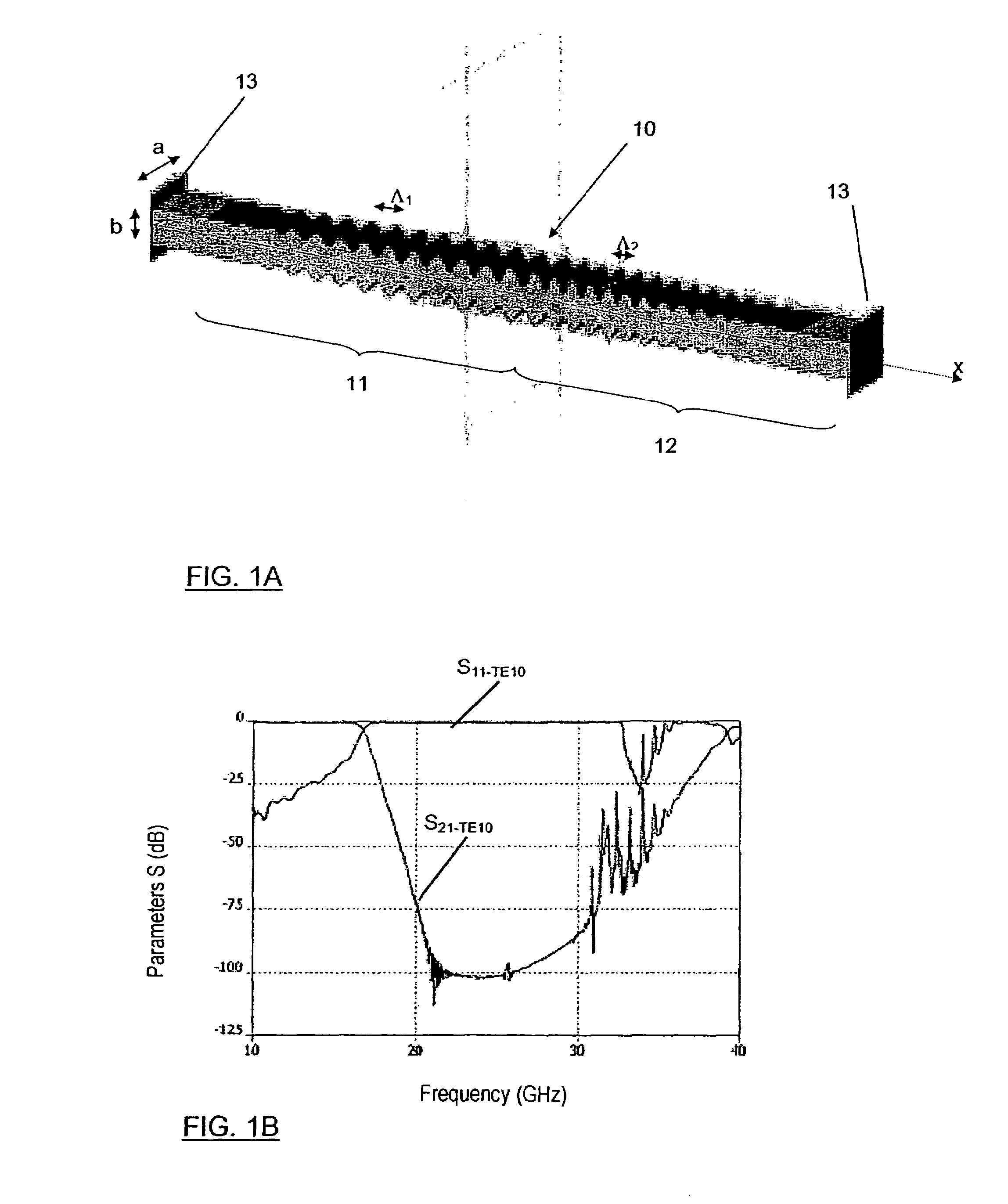
[0038]A bandstop filter of the invention is essentially constituted by a waveguide segment of cross-section that presents longitudinal variation of sinusoidal type, modulated by a continuous amplitude and / or phase function. If the cross-section of the waveguide segment is written S(x), where x is a longitudinal coordinate, it is then possible to write:

S(x)=S0+P(x)·sin[Ω0·x+Φ(s)]  [1]

where:

[0039]S0 is the mean section; and

[0040]P(x)·sin[Ω0·x+Φ(x)] represents the modulated sinusoidal variation.

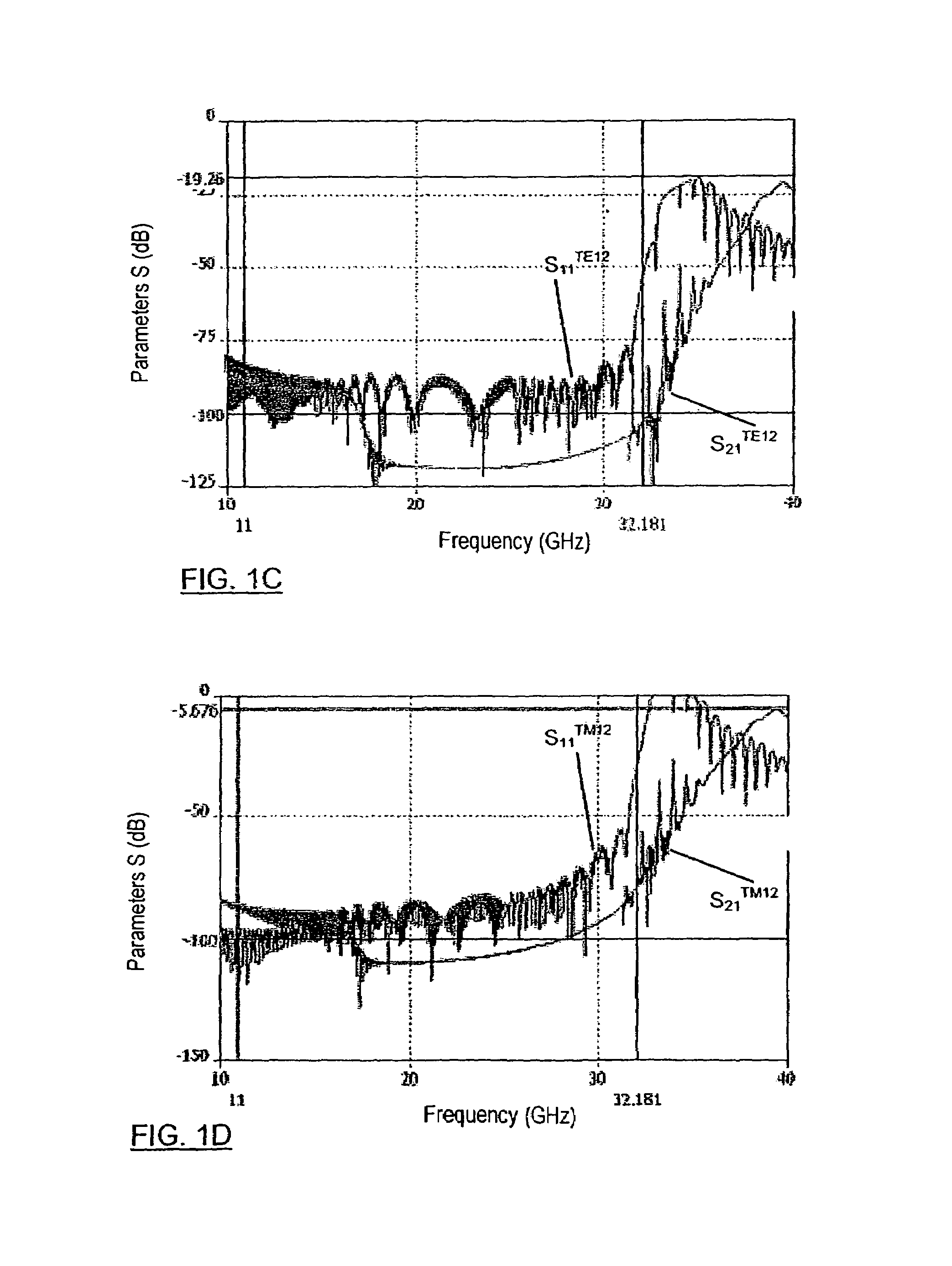
[0041]Advantageously, the filter can be obtained from a waveguide of rectangular section such as, for example, a WR75 waveguide having sides of length a=19.05 millimeters (mm) and b=9.525 mm. Such a waveguide is generally used for propagating TE modes in which the electric field is perpendicular to the longest walls, which are consequently said to be “E-planes”. It is observed that when such a waveguide is used in a band lying in the range 10 GHz to 15 GHz and above, it presents a multimode char...


PUM


Abstract

A microwave bandstop filter comprises a waveguide segment of cross-section that presents longitudinal variation of sinusoidal type modulated by an amplitude function that is continuous, the period of said longitudinal variation of sinusoidal type being the Bragg period for the fundamental guided mode at a center frequency of the band to be stopped. A filter assembly comprises a microwave lowpass filter presenting a cutoff frequency and at least one interfering passband at frequencies higher than said cutoff frequency, and at least one bandstop filter as defined above, connected to the output of said lowpass filter, in which the amplitude and the period of said longitudinal variation, and also the length over which it extends are such that they stop said interfering passband of said lowpass filter. An output multiplexer for a multichannel microwave transmitter includes such a filter assembly.

Description

[0001]The invention relates to a bandstop filter for operating in the microwave region of the spectrum, and more particularly in bands X to K or Ka, and enabling signals to be transmitted at high power, of kilowatt or higher order.[0002]Such a filter is intended particularly, but not exclusively, for application to output multiplexers of transmitters in telecommunications satellites.[0003]The invention also relates to a filter assembly including such a bandstop filter, and to an output multiplexer of a microwave multichannel transmitter including such a filter assembly.BACKGROUND OF THE INVENTION[0004]Microwave transmitters for telecommunications satellites use an output multiplexer (OMUX) for combining the various transmission channels. In modern systems, it can be necessary to combine as many as 18 or more channels, and since the power of each channel in the Ku band (12 gigahertz (GHz) to 18 GHz) generally lies in the range 150 watts (W) to 250 W, the output multiplexer must be ca...

Claims


Application Information

Patent Timeline
Patent Type & Authority Patents(United States)
IPC IPC(8): H01P1/00H01P5/12H01P9/00
CPCH01P1/207
Inventor SOROLLA, MARIOSCHMITT, DIETMARGUGLIELMI, MARCOGIL, JAVIERORTIZ PEREZ DE EULATE, NOELIA
Owner EUROPEAN SPACE AGENCY
Why Eureka
Try Eureka