Window shutter system

a window shutter and window technology, applied in the direction of shutters/movable grilles, construction, building components, etc., can solve the problems of flying debris, limbs, twigs, windows falling off, etc., and achieve the effect of convenient carrying of the devi

Inactive Publication Date: 2008-12-30
STEEL JONATHAN
View PDF7 Cites 27 Cited by
  • Summary
  • Abstract
  • Description
  • Claims
  • Application Information

AI Technical Summary

Benefits of technology

[0007]In a storm, there is a danger of flying debris that may include tree limbs, twigs, and pinecones to name just a few examples. When a small article traveling at a great speed strikes a window, it may fracture the window and submit the occupants of the interior of the building to physical injury as well as damage to the actual physical structure of the building. This device is meant to cover the entire window structure and to be placed over the outside of the window. It will be portable and light weight enough so that most individuals can install it. It will have a quick release button so that it can be easily uninstalled.
[0010]In the interior of the device will be a gear that will allow an individual to tighten as much as possible this device onto the frame structure. A set of exterior knobs will allow the inner gear to be turned to achieve the appropriate tension against the building.
[0012]A handle will allow the device to be carried easily and on the handle will be a button that will move the pawl mechanism from front to back, thereby retracting the protective panes. The shifting of the pawl will allow the gears to be moved and the vanes to be retracted. A spring in the push button mechanism moves the pawl from front to back in the interior of the device.

Problems solved by technology

In a storm, there is a danger of flying debris that may include tree limbs, twigs, and pinecones to name just a few examples.
When a small article traveling at a great speed strikes a window, it may fracture the window and submit the occupants of the interior of the building to physical injury as well as damage to the actual physical structure of the building.
One of the difficulties with similar storm protection devices is maintaining the appropriate tension along the exterior surface of the window frame to insure that the device remains in place particularly during periods of high winds.

Method used


Image

  • Window shutter system
  • Window shutter system
  • Window shutter system

Examples


Embodiment Construction

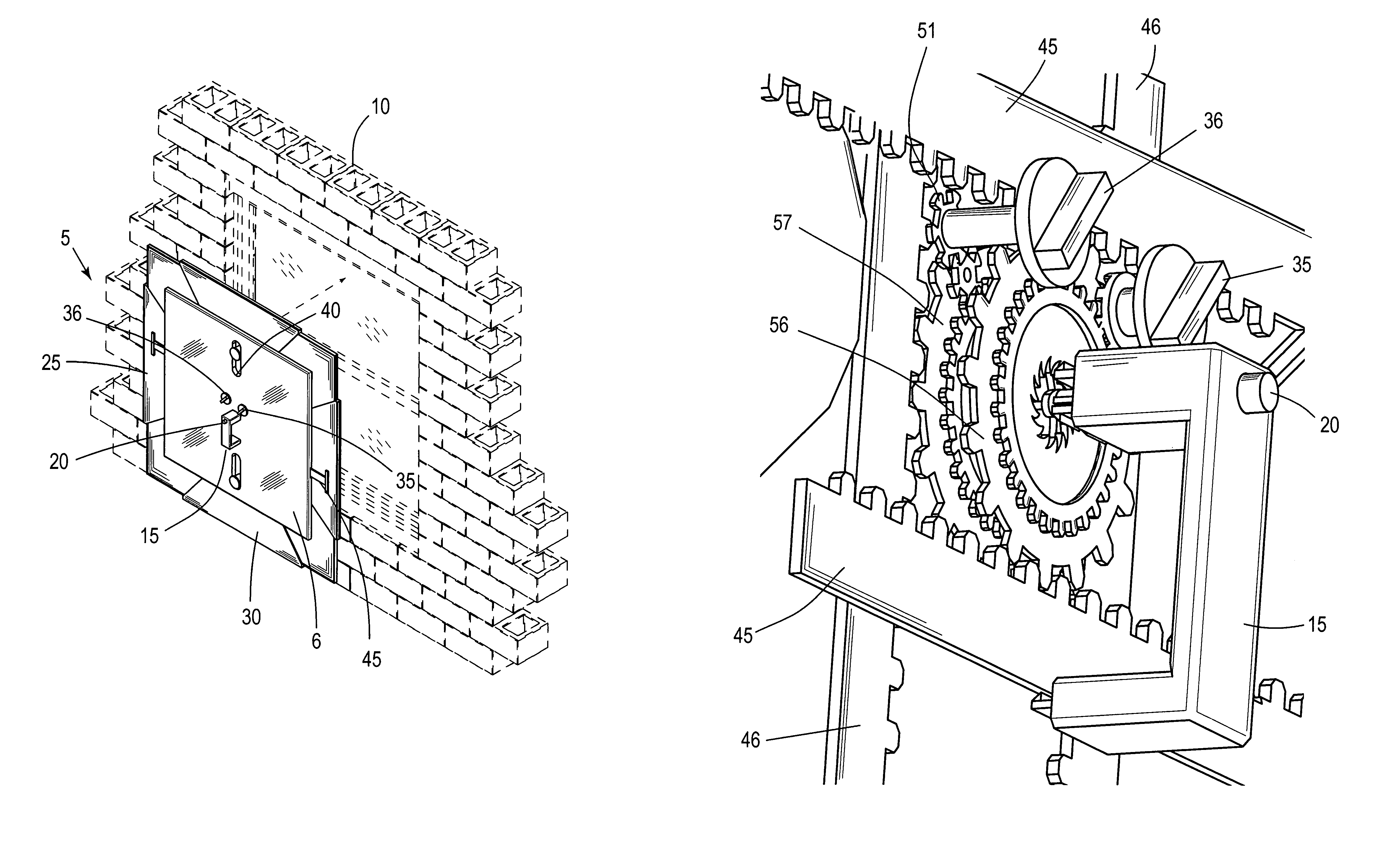
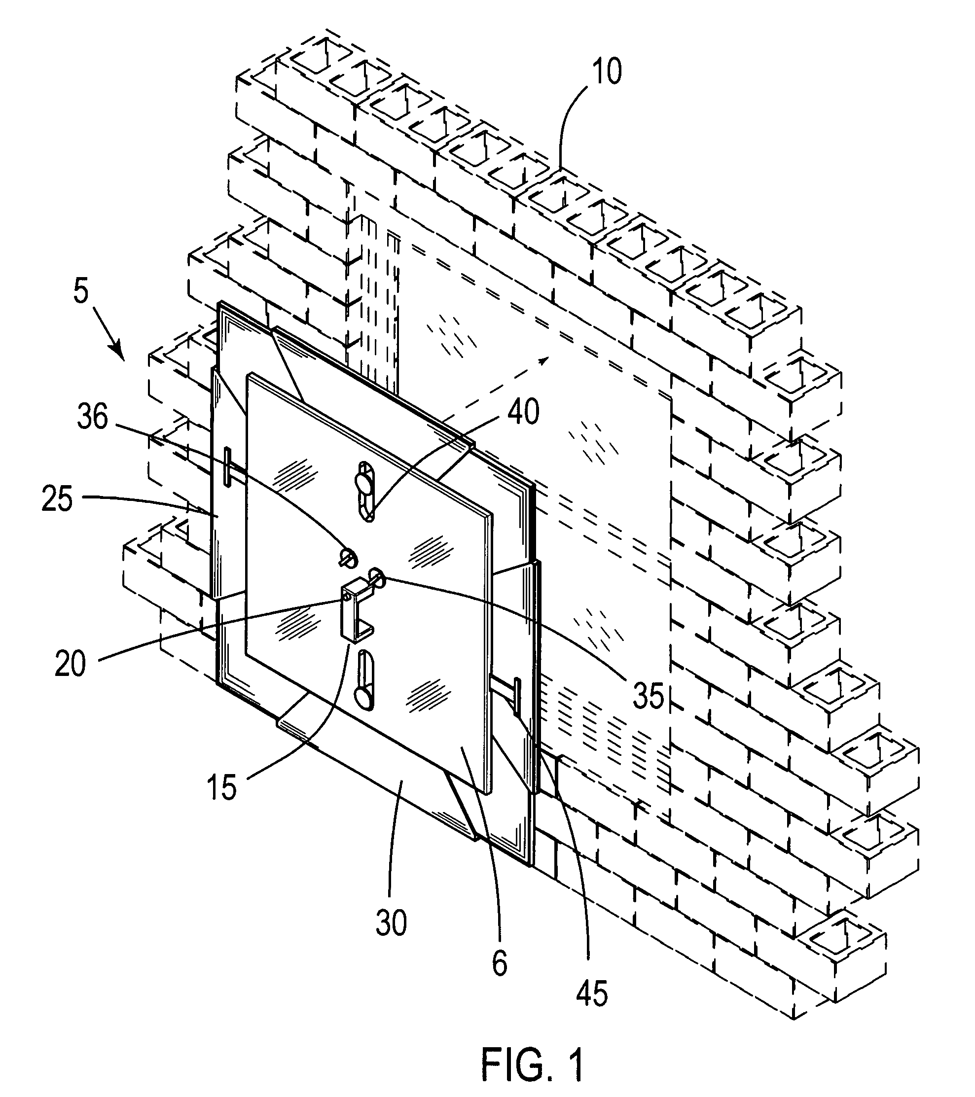
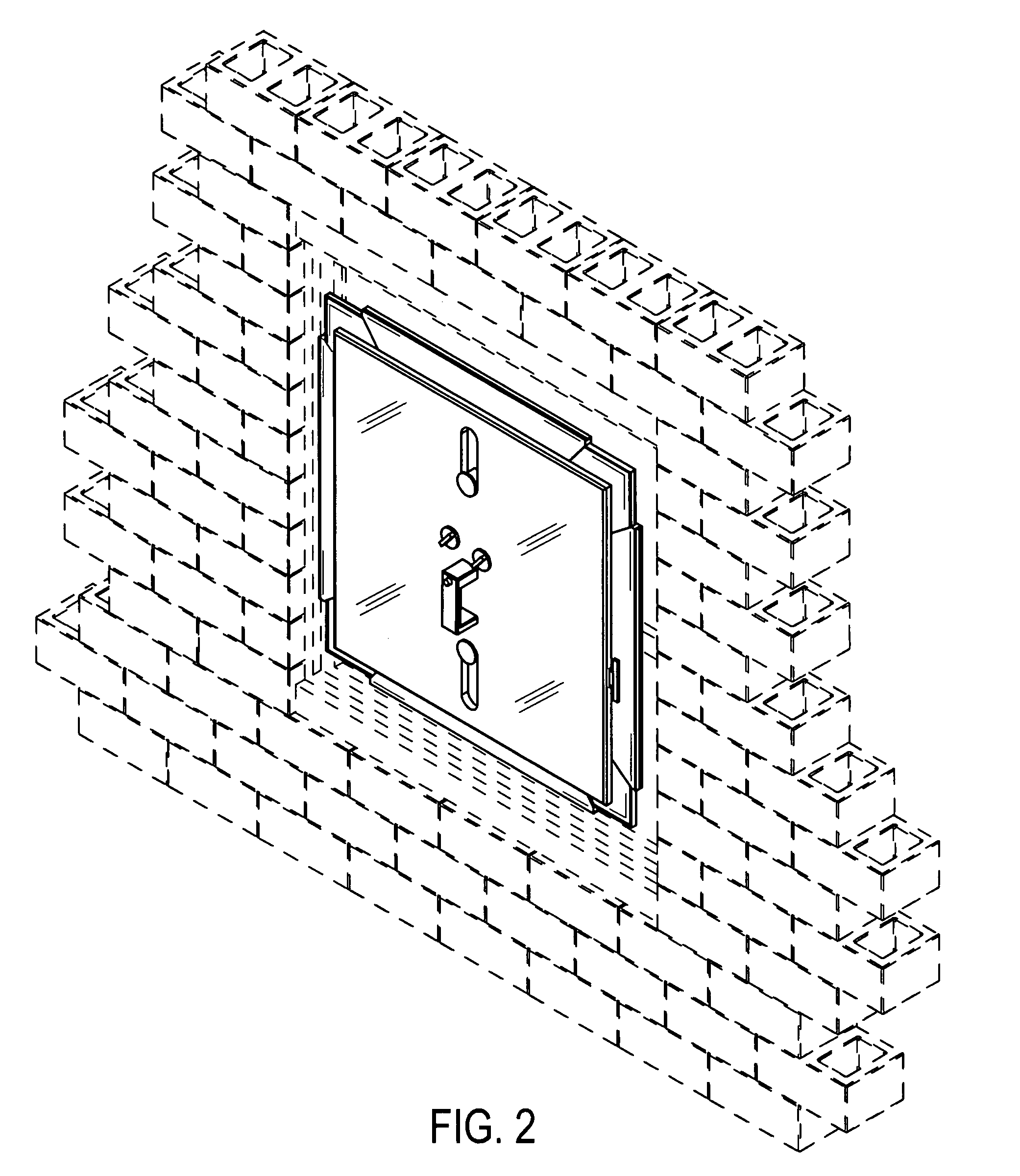
[0026]For purposes of this application, the following numbering will be employed:

[0027]5 device

[0028]6 front surface

[0029]10 building structure

[0030]15 handle

[0031]20 push button release mechanism

[0032]20B first end of the interior release shaft

[0033]20C second end of interior release shaft

[0034]21 release shaft

[0035]25 horizontal panels

[0036]30 vertical panels

[0037]31 panel seal

[0038]35 first exterior turning knob

[0039]36 second exterior turning knob

[0040]40 eliptical opening

[0041]42 connection means for panels

[0042]43 corner panels

[0043]45 horizontal rack member

[0044]46 vertical rack member

[0045]50 gear teeth

[0046]51 turning knob gear

[0047]55 pawl gear

[0048]56 second gear

[0049]57 first gear

[0050]60 pawl

[0051]60T pawl teeth

[0052]61 adjustment knob shaft

[0053]63 release mechanism

[0054]This device is a window shutter system 5. It will be lightweight, portable and easily installed by an individual with very little physical effect. In order to make it lightweight but yet durable a vari...


PUM


Abstract

This is a storm shutter device, which is lightweight, portable and easy to install and un-install. A series of protective panels will extend from the interior of the device to seal the area around the outside of the window. Appropriate tension will be maintained around the window frame through a series of interior gear teeth and a plurality of exterior adjustment knobs. A pawl in the interior of the device insures that the device will remain in place once the device is installed in the area around the window frame.

Description

BACKGROUND OF THE INVENTION[0001]A. Field of the Invention[0002]This relates to the protection of a structure during periods of inclement weather, specifically the protector of windows. One danger during periods of inclement weather is the danger from flying objects as they impact a window. This can be devastating in terms of damage to the window itself as well as to the interior of the structure not to mention any individuals who happen to be in the building.[0003]One of the traditional ways of protecting the windows and therefore protecting the interior is to insert plywood sheets or some other barrier device over the windows. A drawback to the installation of plywood specifically is that when the plywood becomes wet it will warp and, therefore, must be discarded after one use. Another problem with a plywood type structure is the difficulty installing the plywood because of its weight and relatively awkward size. This device is designed to be reusable, is easily installed and cove...

Claims


Application Information

Patent Timeline
Patent Type & Authority Patents(United States)
IPC IPC(8): E05C21/02
CPCE05C9/06E06B9/02E05C9/12E05C19/001E06B2009/005
Inventor STEEL, JONATHAN
Owner STEEL JONATHAN
Why Eureka
Try Eureka