Removable tower sleeve

A tower and sleeve technology, applied in the field of lifting platform, can solve the problems of impossible sleeve/tower structure, high cost, and inability to allow on-site installation.

Inactive Publication Date: 2005-08-17
LES PROD CHIMS FRACO LIMITEE
View PDF4 Cites 16 Cited by
  • Summary
  • Abstract
  • Description
  • Claims
  • Application Information

AI Technical Summary

Problems solved by technology

[0003] Even though some pre-equipped sleeve / tower structures are relatively small, some locations are virtually impossible to reach with pre-equipped sleeve / tower structures, or simply cannot allow their field installation, depending on the surrounding environment, or depending on the Restrictions on building phases at a specific time
[0004] Also, once the lifting devices etc. normally fixed or mounted on the sleeve fail, one needs to dismantle the whole tower or scaffolding structure to remove the sleeve from the tower and repair or replace it, which is really expensive. time, and often at high cost

Method used


Image

  • Removable tower sleeve
  • Removable tower sleeve
  • Removable tower sleeve

Examples


Embodiment Construction

[0044] Description of preferred embodiments

[0045] Preferred embodiments of the invention will now be described, schematically and not limitatively, with reference to the accompanying drawings.

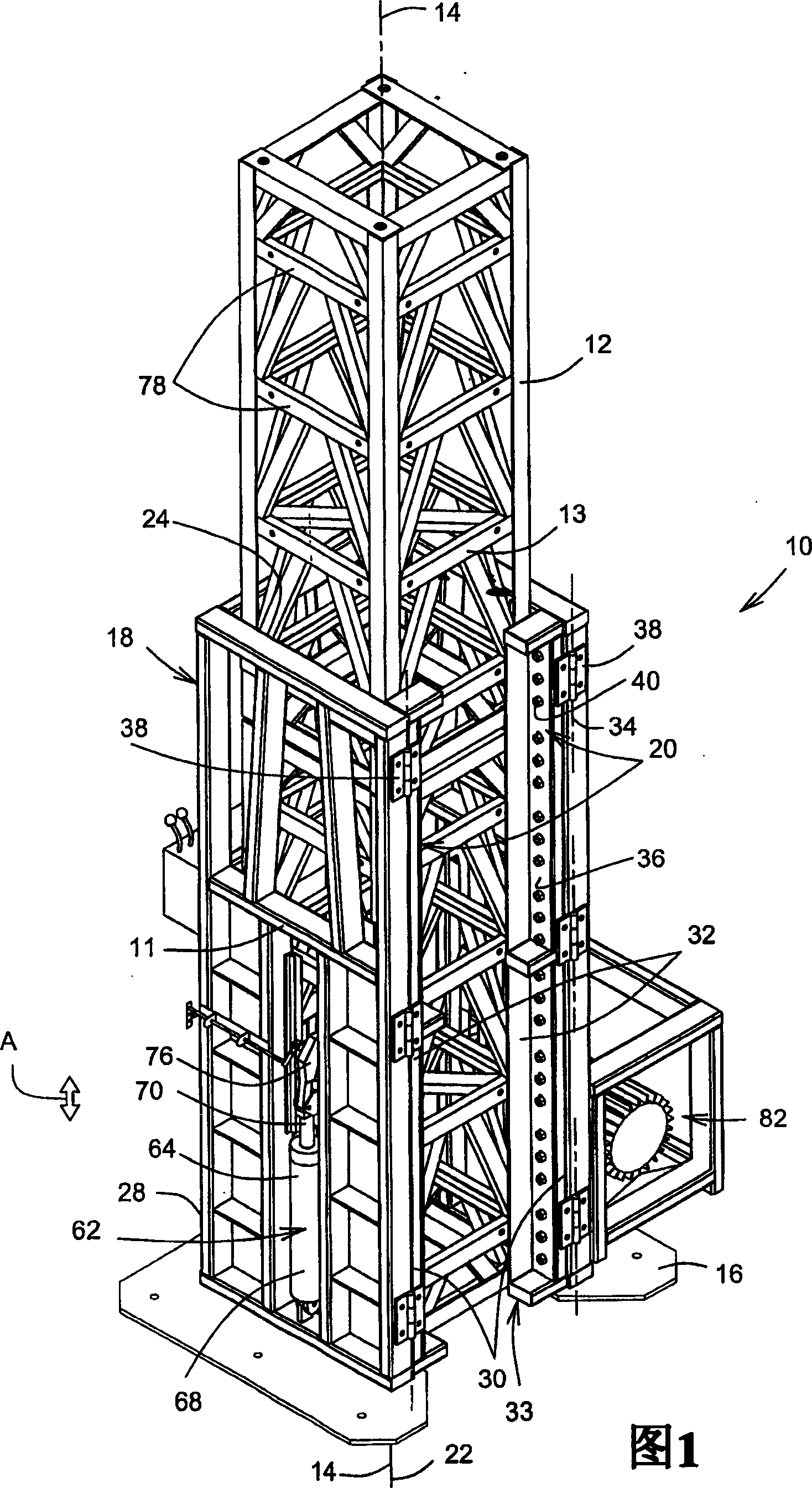
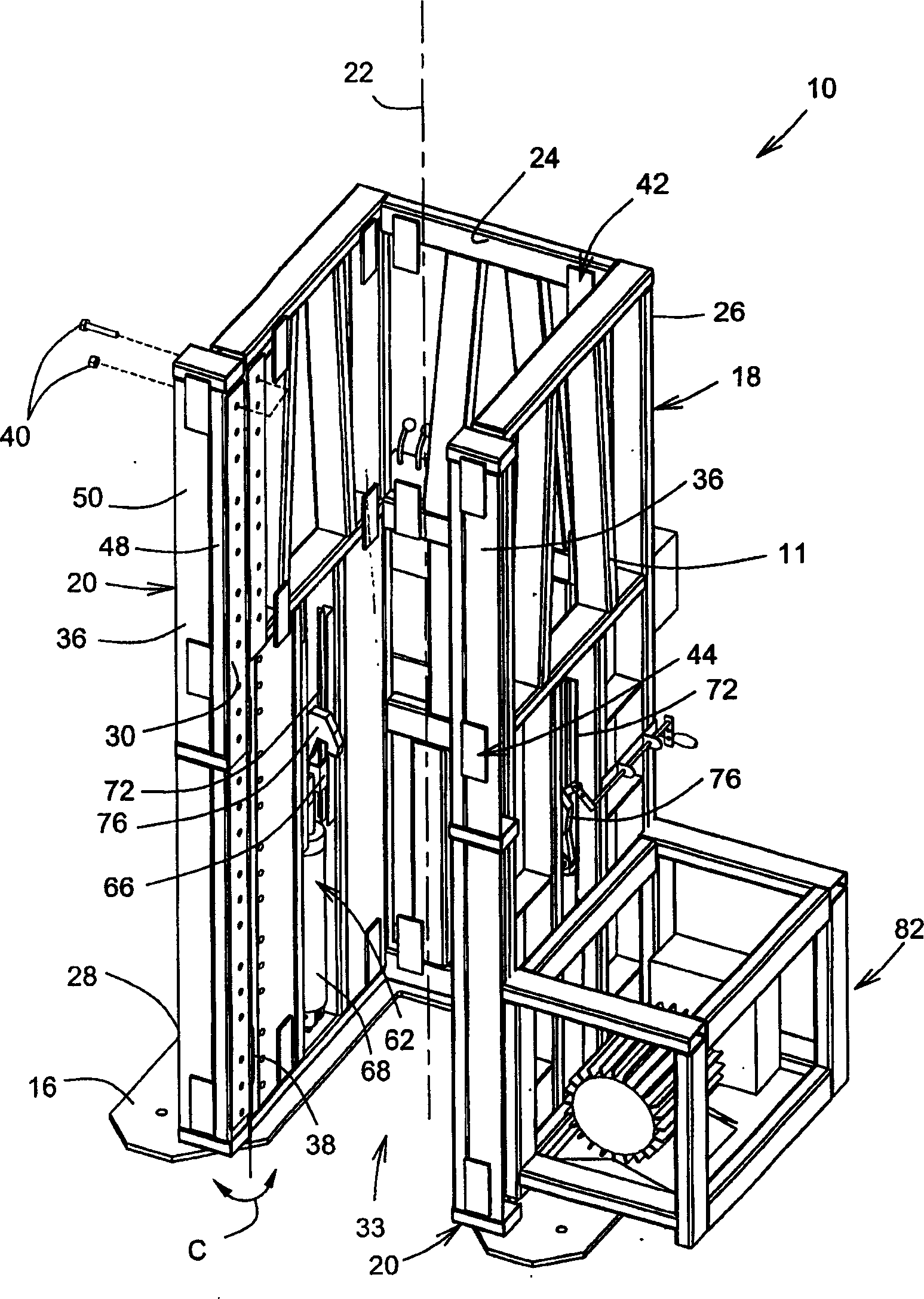
[0046]1 and 2, there is shown an embodiment of a tower sleeve 10 according to the present invention for sliding engagement with a conventional tower 12 or mast using scaffolding or the like, the tower 10 defining a tower longitudinal axis 14 and a A tower longitudinal side wall 13 substantially parallel to the tower longitudinal axis 14 . A tower sleeve 10 for guiding up and down movement along the tower 12 (as shown by the arrow in FIG. 1 ) is used to detachably and firmly support a platform (not shown) etc. on the interface plate structure 16, Such as US Patent No. 5,159,993 authorized to St-Germain on November 3, 1992, US Patent No. 5,746,290 authorized to St-Germain et al. on May 5, 1998, or authorized to St-Germain on November 6, 2001 shown in US Patent No. 6,311,800 to et al...


PUM


Abstract

A self-erecting tower crane (20) for use on a construction site is supported at a top end (102) of a tower (26) that includes tower sections (114) assembled in an end-to-end relationship relative to one another along a tower axis (38). The tower crane (20) includes a boom assembly (28) for selectively raising tower sections (114) above ground. A boom support structure (24) has an upper portion (30) that rotatably supports the boom assembly (28) relative to the tower axis (38), and a lower portion (32) that is configured and sized for mounting on and releasably securing to the tower top end (102). A self-raising sleeve (22) mounts on the tower (26) for axial movement therealong, and selectively and releasably supports the boom support structure (24) on the tower (26). The sleeve (22) and the boom support structure (24) include a side opening (116) that is configured and sized for allowing a tower section (114) to be assembled to the tower top end (102) for the self-erection of the tower crane (20).A tower (10) for selectively supporting an elevator (12) thereon includes an elongated structure (14) that slidably supports the elevator (12) therealong. The elongated structure (14) defines a structure axis (16) and includes at least two generally opposed first and second longitudinal structure sidewalls (18,20). Generally elongated first and second elevator retaining guides (22,24) releasably secure to the first and second structure sidewalls (18,20), respectively, for guiding and retaining the elevator (12) along the elongated structure (14). The first and second retaining guides (22,24) extend generally radially outwardly from the elongated structure (14).

Description

technical field [0001] The present invention relates to a lifting platform and, more particularly, to a sleeve or platform that can be removed from a tower to which it is mounted for placement along. Background technique [0002] Lifting tables or sleeves are well known in the construction arts, as in US Patent No. 5,159,993, issued November 3, 1992 to St-Germain, US Patent issued May 5, 1998 to St-Germain et al. No. 5,746,290 or as disclosed in US Patent No. 6,311,800 issued November 6, 2001 to St-Germain et al. Sleeves comprising fixed (eg transport elevators etc.) or detachable platforms are generally available pre-equipped to the lower part of the tower or mast on which they are to be placed. Alternatively, the sleeve needs to be slidably lowered to the lower part of the tower using a crane or the like. [0003] Even though some pre-equipped sleeve / tower structures are relatively small, some locations are virtually impossible to reach with pre-equipped sleeve / tower str...

Claims


Application Information

Patent Timeline
Patent Type & Authority Applications(China)
IPC IPC(8): B66B7/02B66B9/187B66C23/28B66F11/04E04G1/20
CPCB66F11/04E04G1/20B66B9/187B66B7/027B66C23/283
Inventor 安德烈·圣-杰曼
Owner LES PROD CHIMS FRACO LIMITEE
Why Eureka
Try Eureka