Front floor frame

a floor frame and front frame technology, applied in the field of automobiles, can solve the problems of increasing the cost of the vehicle, increasing the tooling cost, and not constant distance between the longitudinal frame member 104 and the adjacent side sill 106

Active Publication Date: 2008-12-30
HONDA MOTOR CO LTD
View PDF15 Cites 76 Cited by
  • Summary
  • Abstract
  • Description
  • Claims
  • Application Information

AI Technical Summary

Problems solved by technology

One disadvantage to the conventional floor frame 102 is that the distance between each longitudinal frame member 104 and the adjacent side sill 106 is not constant.
This in turn increases tooling costs thereby increasing the cost of the vehicle.
Another disadvantage to the conventional floor frame 102 is the distance d2 between the longitudinal frame members 104.
Still yet another disadvantage to the conventional floor frame 102 is the dispersion of the energy load paths in the event of a frontal impact.

Method used


Image

  • Front floor frame
  • Front floor frame
  • Front floor frame

Examples


Embodiment Construction

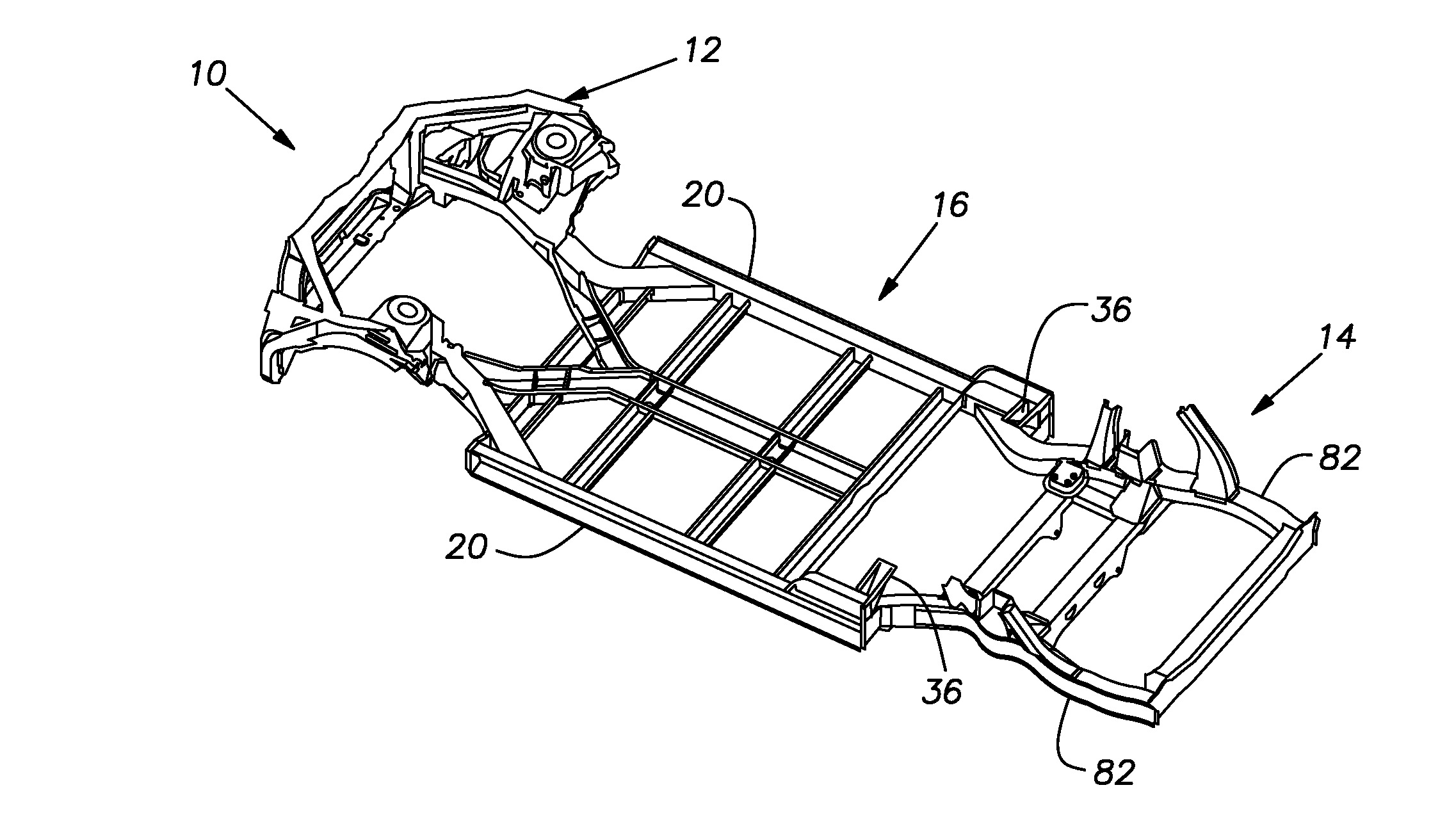
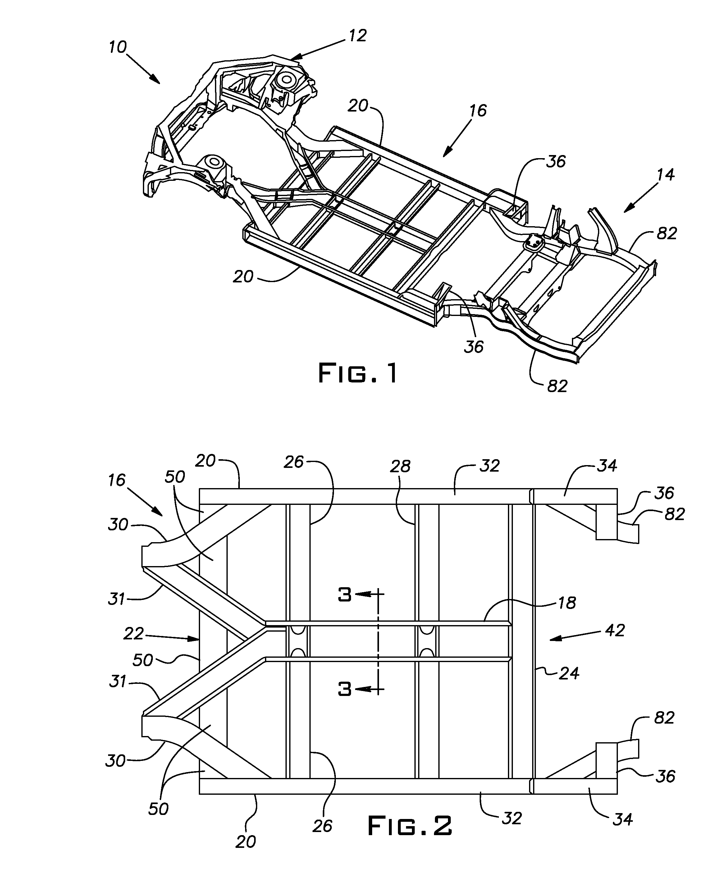
[0023]Referring now to the drawings, FIG. 1 shows a vehicle body structure 10 having a front frame 12, a rear frame 14 and a floor frame 16. It should be noted that in the accompanying drawings, “front,”“rear,”“left,”“right,”“up,” and “down” indicate directions as viewed from the driver's position. Further, the front frame 12 and rear frame 14 are of the type commonly known in the art and will not be described herein.

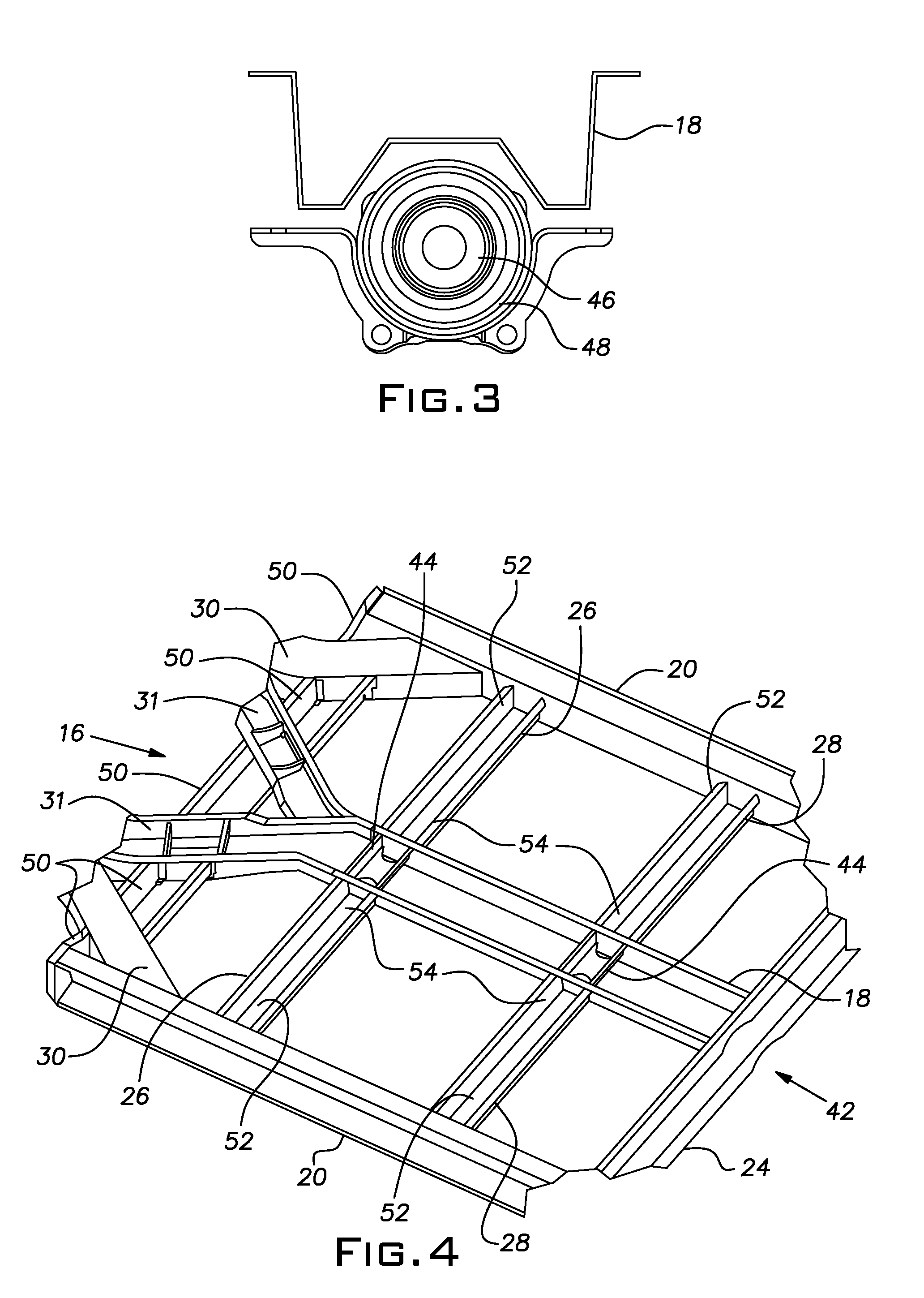
[0024]Referring to FIGS. 1 and 2, the floor frame 16 has three-substantially parallel longitudinal frame members including a center frame 18, and a pair of side sills 20 located on opposite sides of the center frame 18. The floor frame 16 further includes multiple-substantially parallel cross members including a front cross member 22, a rear cross member 24, two front-central cross members 26 and two rear-central cross members 28. The floor frame 16 still further includes multiple branch members including two side branch members 30 and two center branch members 31 that ...


PUM


Abstract

A floor frame for an automotive vehicle is provided and includes a longitudinal center frame member having a W-shaped cross section, two longitudinal side frame members having C-shaped cross sections, a front cross member, a rear cross member and a first pair of central cross members, two side branch members and two center branch members all having U-shaped cross sections. Each side branch member is attached to a front frame and extends from the front frame at a downward and outward angle and connects to each side frame member. Each center branch member is attached to the front frame and extends from the front frame at a downward and inward angle and connects to a first end of the center frame thereby forming a first Y-joint. The connection of the side branch and the center branch to the front frame form a pair of second Y-joints.

Description

BACKGROUND OF THE INVENTION[0001]1. Field of the Invention[0002]The present invention relates to an automotive vehicle and more specifically to an improved floor frame for an automotive vehicle.[0003]2. Description of Related Art[0004]Referring to FIG. 11, a vehicle body structure 100 having a conventional floor frame 102 is illustrated. The floor frame 102 includes four longitudinal frame pieces including two longitudinal frame members 104 and two side sills 106, multiple cross members 108, multiple outriggers 110, and a center reinforcement member 112. The cross members 108 extend between the longitudinal frame members 104 and the outriggers 110 extend between the longitudinal frame members 104 and the side sills 106.[0005]One disadvantage to the conventional floor frame 102 is that the distance between each longitudinal frame member 104 and the adjacent side sill 106 is not constant. In other words, the distance between each longitudinal frame member 104 and the adjacent side sil...

Claims


Application Information

Patent Timeline
Patent Type & Authority Patents(United States)
IPC IPC(8): B60J7/00
CPCB62D21/02B62D21/15B62D25/025B62D25/082B62D25/088B62D25/2018B62D25/2027B62D25/2036
Inventor BOETTCHER, ERIC
Owner HONDA MOTOR CO LTD
Why Eureka
Try Eureka