In situ mixing in microchannels

a microchannel and microchannel technology, applied in the field of microchannel mixing, can solve the problems of inability to infer the optimal momentum flux ratio range of good mixing, and the inability to calculate the momentum flux of the second reactant, etc., to reduce the flammability of the mixture, and reduce the effect of flammability

Inactive Publication Date: 2008-12-30
VELOCYS INC
View PDF39 Cites 18 Cited by
  • Summary
  • Abstract
  • Description
  • Claims
  • Application Information

AI Technical Summary

Problems solved by technology

Therefore momentum flux for the second reactant cannot be calculated from these examples, and no optimal momentum flux ratio ranges for good mixing can be inferred.

Method used


Image

  • In situ mixing in microchannels
  • In situ mixing in microchannels
  • In situ mixing in microchannels

Examples


Embodiment Construction

Mixing Prior to a Reaction Zone

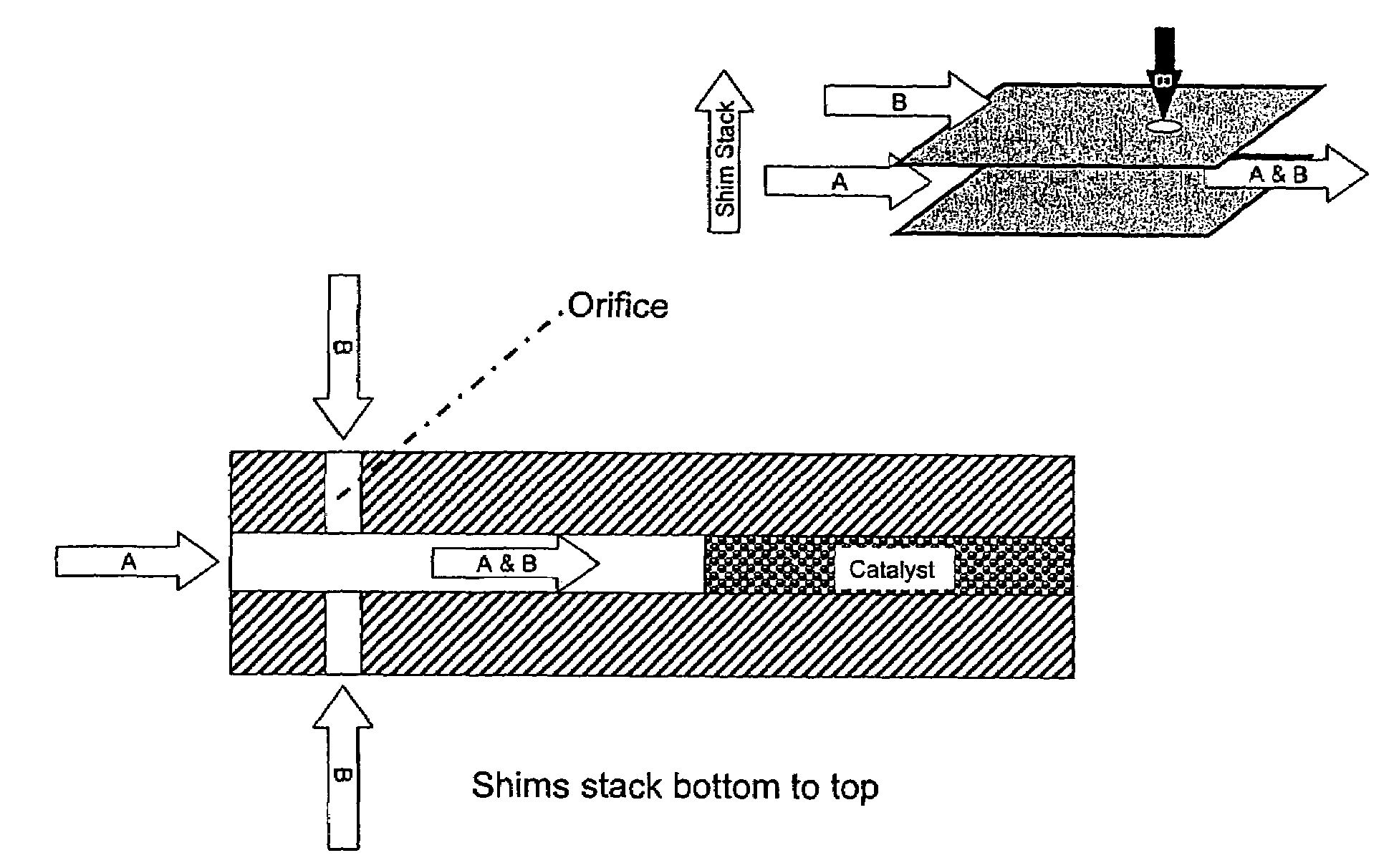
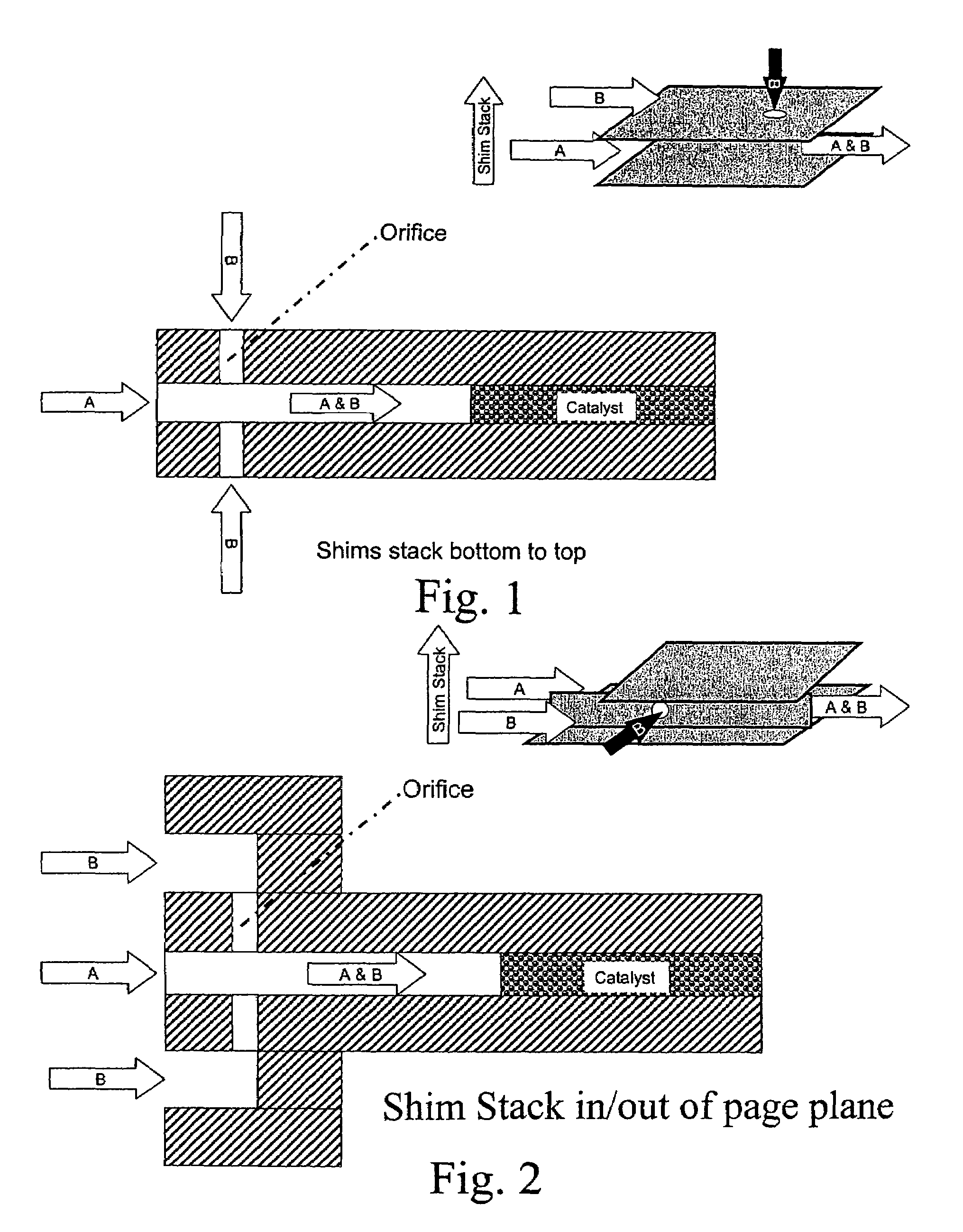
[0058]The mixing of reactants, such as oxidants and hydrocarbons, may occur upstream of a reaction chamber, preferably within a microchannel either immediately upstream from the catalyst zone or further upstream and separated by a heat exchange section or by another section for conducting a first reaction or a separation. It may be advantageous to mix streams, such as methane and oxygen, immediately after entering a device at low temperature. The combined flammable mixture may then flow through an integral heat exchanger to raise the mixture temperature prior to entering a catalytic zone housed within the contiguous microchannel.

[0059]In some embodiments, otherwise explosive mixtures can be safely handled inside microchannels due to quenching at the microchannel walls that prevents explosions or thermal runaway. The mixture may undergo additional heat exchange to raise or cool the temperature as desired. The mixture also may not undergo additional heat...


PUM

PropertyMeasurementUnit
distanceaaaaaaaaaa
velocityaaaaaaaaaa
angleaaaaaaaaaa

Abstract

The present invention provides methods, systems and apparatus in which one fluid passes through an orifice or orifices and mixes with another fluid as it flows through a microchannel.

Description

RELATED APPLICATIONS[0001]In accordance with 35 U.S.C. sect. 119(e), this application claims priority to U.S. Provisional Application No. 60 / 531,006, filed Dec. 18, 2003, which is incorporated herein as if reproduced in full below.FIELD OF THE INVENTION[0002]This invention relates to mixing in microchannels.Introduction[0003]Mixing of one fluid into another is a process that is critically important to a wide variety of chemical processes. Because it is of fundamental importance, great efforts have been made over many, many years to improve mixing quality and speed. For processes that require explosive combinations of reactants, safety is another, extremely important consideration. One example of mixing two fluids can be found in U.S. Pat. No. 6,471,937. In this patent, Anderson et al. describe mixing a first reactant with a second reactant at a high velocity (preferably greater than 300 m / s) and short contact time (preferably less than 0.5 milliseconds) before passing the mixture in...

Claims


Application Information

Patent Timeline
Patent Type & Authority Patents(United States)
IPC IPC(8): B01J8/06B01J10/00B01J19/24B01F23/10B01F23/30B01J19/00
CPCB01F5/0475B01F5/0691B01F13/0059B01J19/0093B01L3/502715B01F5/0682B01L2400/04B01F2215/0427B01F2215/0431B01J2219/00783B01J2219/00822B01J2219/00824B01J2219/00835B01J2219/00844B01J2219/0086B01J2219/00873B01J2219/00889B01J2219/00891Y10T137/0329B01F25/3142B01F25/4522B01F25/45B01F33/30
Inventor TONKOVICH, ANNA LEEJAROSCH, KAIHESSE, DAVID J.FITZGERALD, SEAN P.
Owner VELOCYS INC
Why Eureka
Try Eureka