Cable support assembly for minimizing the bend radius of cables

Active Publication Date: 2008-12-30
ARLINGTON INDS
View PDF7 Cites 34 Cited by
  • Summary
  • Abstract
  • Description
  • Claims
  • Application Information

AI Technical Summary

Benefits of technology

[0012](5) The closing mechanism is releasable, thereby enabling lowering of one side of the cable tray when released. As a result the cable tray sections continue to support the cables in the lowered position. This provides enhanced protection of the cables or cable bundles over prior art cable

Problems solved by technology

Bending or sagging of conductors can adversely affect the data transmission rate, which becomes ver

Method used


Image

  • Cable support assembly for minimizing the bend radius of cables
  • Cable support assembly for minimizing the bend radius of cables
  • Cable support assembly for minimizing the bend radius of cables

Examples


Embodiment Construction

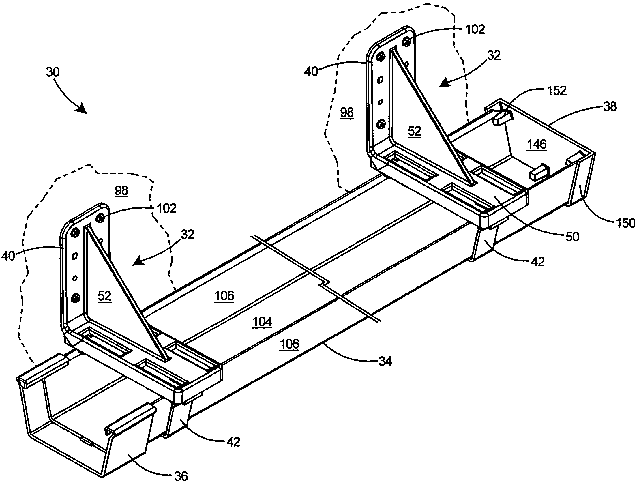
[0047]With reference to FIG. 27 there is shown a preferred embodiment of a cable support assembly 30, which includes a plurality of brackets 32 and one or more elongated cable trays 34. The cable support assembly 30 can further include a coupler 36 for securing cable trays 34 together at their ends and an end cap 38 for terminating the end of a cable tray 34.

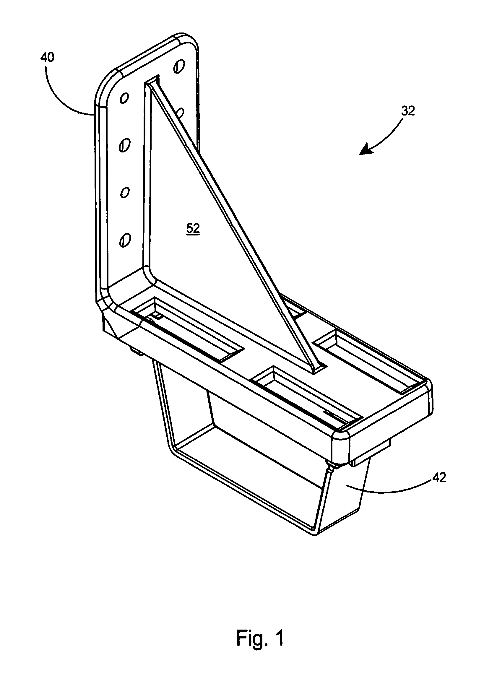
[0048]With reference to FIG. 1 there is shown a preferred embodiment of a bracket 32 according to the present invention. The bracket 32 includes an L-shaped frame member 40 and a hinge arm 42.

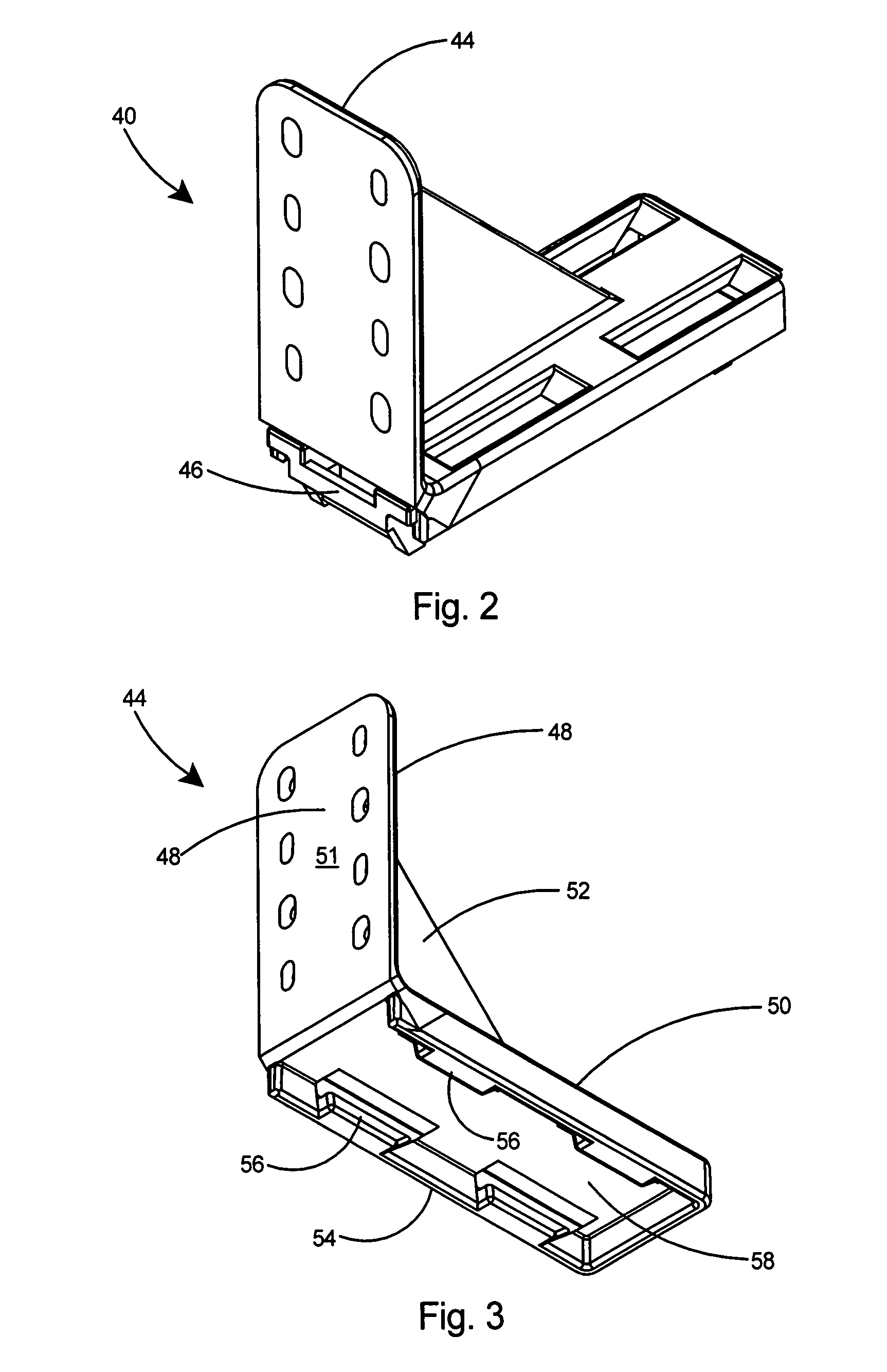
[0049]Referring to FIG. 2, the frame member 40 includes a top portion 44 and a bottom portion 46. The top portion 44 and bottom portion 46 are preferably each molded of plastic in one piece.

[0050]Referring to FIGS. 3-7 there are shown various views of an especially preferred embodiment of the top portion 44 of the bracket. As shown in FIG. 3, the top portion 44 includes a vertical arm 48 and a horizontal arm 50. The outer side of the vertic...


PUM


Abstract

A cable support assembly for routing electrical, communication, or data cables throughout a building. The cable support assembly includes cable trays and brackets for securing the cable trays to a vertical surface. Tray couplers are provided for coupling trays together. The brackets include an L-shaped support member and a hinge arm pivotally attached to the support member. The hinge arm portion of the bracket may be rotated downwards for loading of a cable tray therein and then rotated upwards and latched to the base members to lock the cable tray in place. Ninety-degree bend and T-shaped cable tray sections are also provided. Adjacent cable tray sections may be joined with couplers to create a cable raceway or support assembly in which the cable tray provides support for any electrical, communication, or data cables installed therein.

Description

[0001]This application is a Continuation-In-Part of U.S. patent application Ser. No. 11 / 471,151 filed Jun. 20, 2006 now U.S. Pat. No. 7,304,204 the entire contents of which are incorporated herein by reference.FIELD OF THE INVENTION[0002]This invention relates to cable supports and specifically to a cable support assembly or cable raceway that supports electrical cables in such a manner that the bend radius of individual cables is minimized.BACKGROUND OF THE INVENTION[0003]Cable raceways are used for supporting high or low voltage cables in residences and commercial buildings. One such cable raceway system was proposed in U.S. patent application Ser. No. 11 / 471,151, which shares common ownership and inventorship with the present invention and has been incorporated herein by reference thereto. The cable raceway system of the parent application included a cable tray that was supported from an overhead support that included a pivoting hinge arm. The hinge arm was capable of being relea...

Claims


Application Information

Patent Timeline
IPC IPC(8): H02G3/04
CPCH02G3/0608H02G3/32
Inventor GRETZ, THOMAS J.
Owner ARLINGTON INDS
Why Eureka
Try Eureka