Key structure

a technology of key structure and ring, which is applied in the direction of moving contacts, emergency actuators, emergency contacts, etc., can solve the problems of reducing the accuracy of aligning the metal dome, affecting the function of the transparent thin film b, and affecting the accuracy of the metal dome alignment, so as to eliminate limitations or defects, the effect of high manufacturing cos

Inactive Publication Date: 2008-12-30
ALTEK CORP
View PDF12 Cites 22 Cited by
  • Summary
  • Abstract
  • Description
  • Claims
  • Application Information

AI Technical Summary

Benefits of technology

[0010]Accordingly, the object of the present invention is to provide a key structure, which eliminates the limitations or defects of over high manufacturing cost and too much space occupied by the key switches of the prior art.
[0012]The function of the present invention is that the control member can be selectively disposed on different types of contact members according to the electrical requirements in actual applications, such that the objects of simple and fast assembling, significantly reduced occupied space, and lower manufacturing cost are achieved.

Problems solved by technology

After having been used for a long time, the functionality of the transparent thin film 13 may get lost because of the deterioration of the material, which leads to lower accuracy during the aligning of the metal dome 11.
Furthermore, the application of the transparent thin film 13 incurs additional manufacturing cost.
As shown in FIG. 1B, the rubber module applied in the conventional rubber switch occupies too much space during the assembling, thus the positions for other electronic components are limited, which doesn't comply with the requirements that electronic devices shall be light and thin currently.
Furthermore, the rubber material 20 for fabricating the rubber switch module also constitutes a burden to the manufacturers.

Method used


Image

  • Key structure
  • Key structure
  • Key structure

Examples


first embodiment

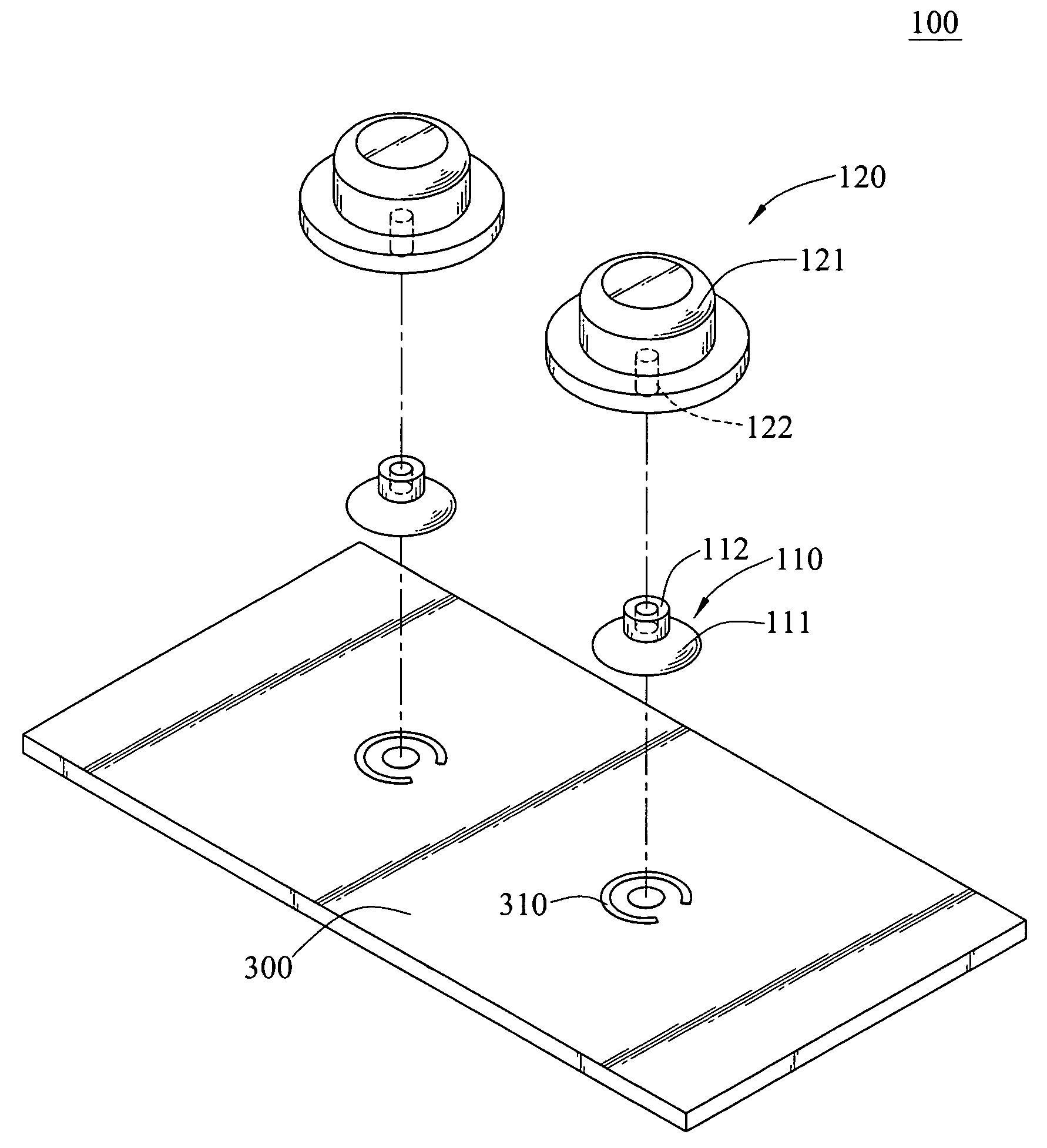
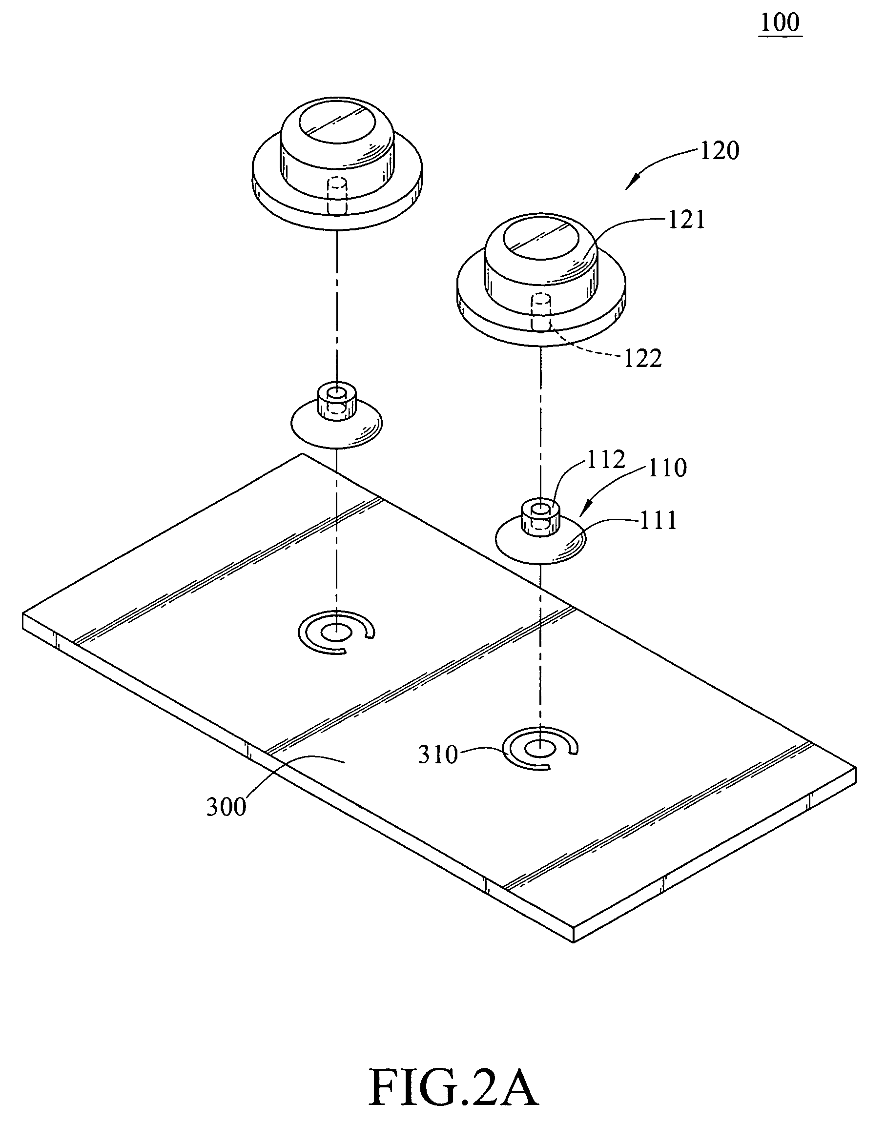
[0028]As shown in FIG. 2A and FIG. 2B, the present invention discloses the implementation of a dome switch. As shown in the figures, the elastic portion 111 of the contact member 110 is a metal dome. When the user presses the control member 120, the metal dome is pushed to be in electrical contact with the electric contact 310 to output a corresponding signal. When the user releases the control member 120, the combining portion 122 combined in the fixed portion 112 returns to the release position with the elastic force of the elastic portion 111 of the contact member 110, that is, the control member 120 is suspended at a corresponding position of the electric contact 310. As the control member 120 is directly disposed on the contact member 110, the uniformity of the dome switch when exerting a force is improved, thus the limitation of low aligning performance of the conventional dome switch is prevented.

second embodiment

[0029]As shown in FIG. 3A and FIG. 3B, the present invention discloses the implementation of a rubber switch. As shown in the figures; the elastic portion 111 of the contact member 110 is made of a rubber material, and a conductive rubber 1111 is disposed in the elastic portion 111. When the user presses the control member 120, the conductive rubber 1111 is pushed to be in electrical contact with the electric contact 310 to output a corresponding signal. When the user releases the control member 120, the combining portion 122 combined in the fixed portion 112 returns to the release position because of the elastic feature of the elastic portion 111, that is, the control member 120 is suspended at a corresponding position of the electric contact 310.

[0030]As shown in FIGS. 4A and 4B, the combining of the contact member 110 and the control member 120 can be realized by screw thread fitting. The combining portion 122 of the control member 120 has an external thread 1221, and the fixed p...


PUM


Abstract

A key structure is provided, which includes a plurality of contact members and a control member. Each of the contact members has an elastic portion and a fixed portion, and the control member has a pressing portion and a combining portion. The control member is selectively combined with an appropriate contact member according to actual requirements in the electrical connection.

Description

CROSS-REFERENCE TO RELATED APPLICATIONS[0001]This non-provisional application claims priority under 35 U.S.C. §119(a) on Patent Application No(s). 095213165 filed in Taiwan, R.O.C. on Jul. 26, 2006,the entire contents of which are hereby incorporated by reference.BACKGROUND OF THE INVENTION[0002]1.Field of Invention[0003]The present invention relates to a key structure, and more particularly, the present invention relates to a key structure outputting a signal with a control member through contact members combined with the control member.[0004]2.Related Art[0005]Key structures are required in consumer electronics in daily life and in large industrial processing equipments as the media to control the electronics and processing equipments. Conventional key structures are normally classified into dome switches and rubber switches.[0006]FIG. 1A is a schematic stereogram of a dome switch according to the prior art. A metal dome 11 is disposed on an electric contact 31 of a circuit board ...

Claims


Application Information

Patent Timeline
Patent Type & Authority Patents(United States)
IPC IPC(8): H01H3/12
CPCH01H13/12H01H13/70H01H2205/002H01H2205/022H01H2221/066
Inventor LIN, TZU-CHIH
Owner ALTEK CORP
Why Eureka
Try Eureka