Vacuum belt assembly to drive tubular bag material

a vacuum belt and tubular bag technology, applied in conveyors, feeders, successive articles, etc., can solve the problem of reducing the area available for the product to mov

Inactive Publication Date: 2009-01-06
TNA AUSTRALIA
View PDF11 Cites 46 Cited by
  • Summary
  • Abstract
  • Description
  • Claims
  • Application Information

AI Technical Summary

Problems solved by technology

The above-described belt arrangements have the disadvantage that they change the configuration of the tubular bag material to the extent that it reduces the area available for the product to move when being delivered to the interior of the tubular bag material.

Method used


Image

  • Vacuum belt assembly to drive tubular bag material
  • Vacuum belt assembly to drive tubular bag material
  • Vacuum belt assembly to drive tubular bag material

Examples


Embodiment Construction

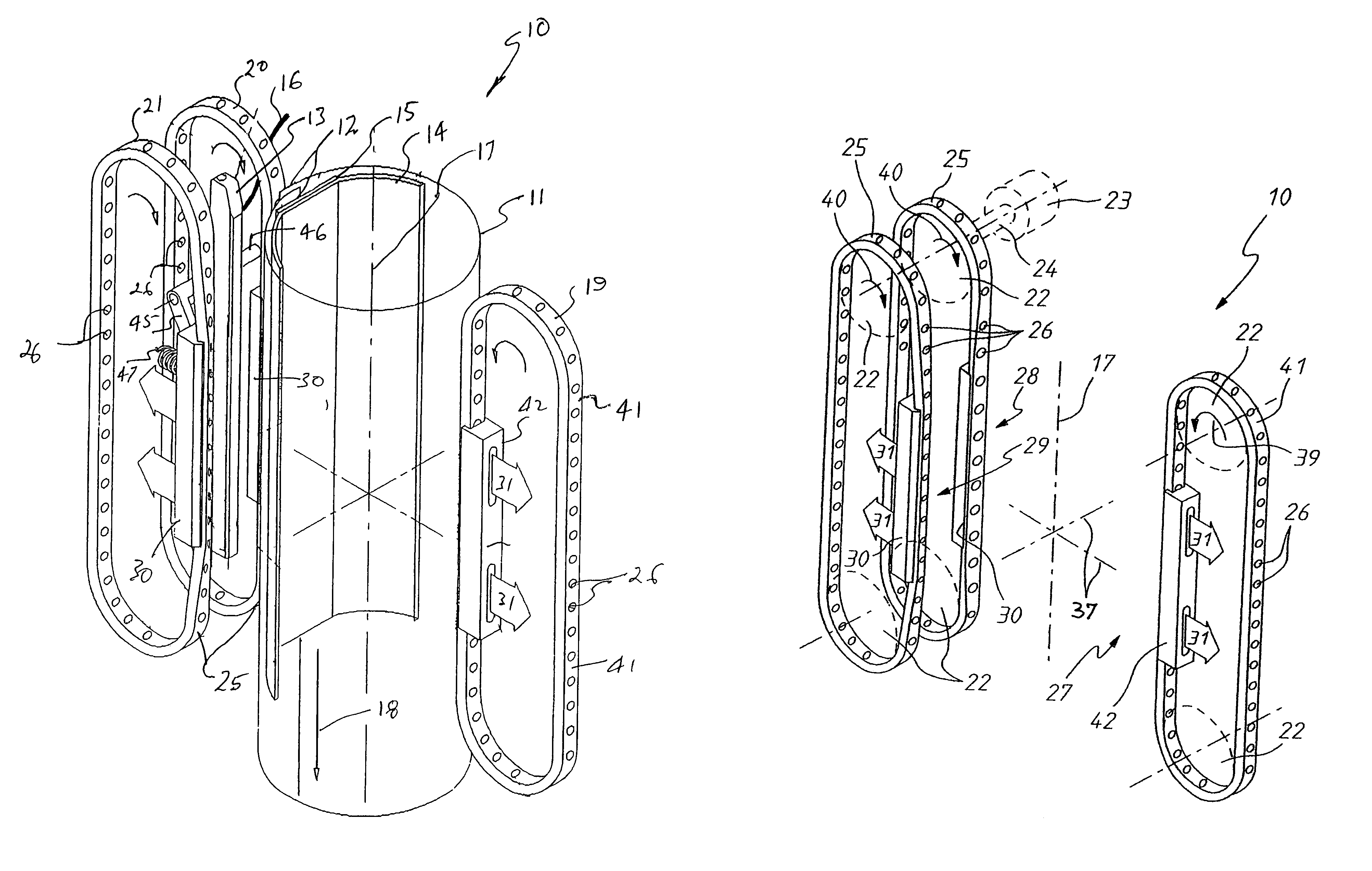
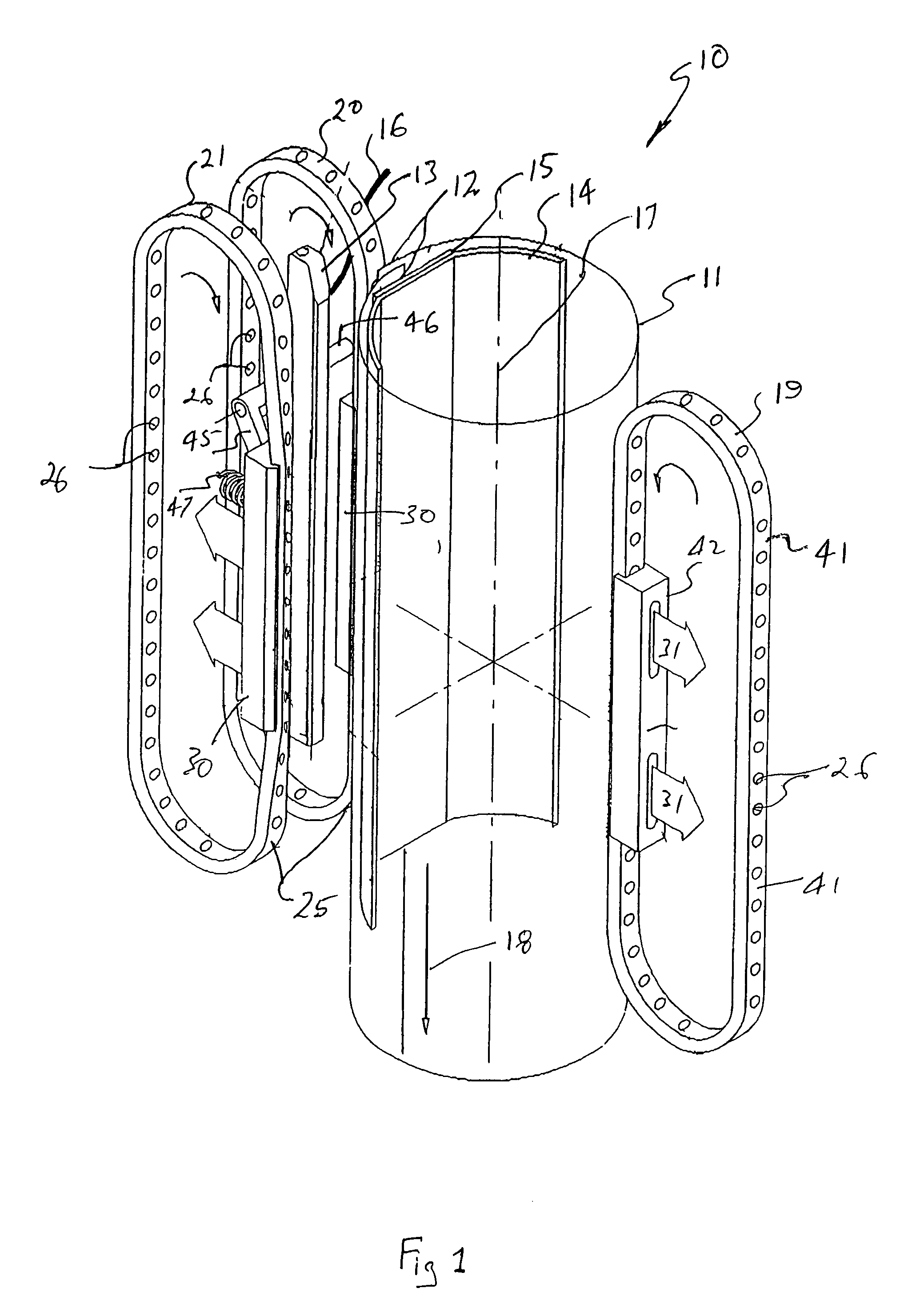
[0023]In the accompanying drawings, there is schematically depicted a vacuum belt assembly 10 to drive tubular bag material 11 through a packaging machine. The tubular bag material 11 has longitudinally extending overlapping edge portions 12 that are sealed so as to be joined. The edge portions 12 are sealed by a backseal bar 13 that is electrically heated and pressed against the overlapping edge portions 12. More particularly, the edge portions 12 are sandwiched between the backseal bar 13 and an inner support 14 to which a Teflon wear strip 15 is attached. An electric lead 16 delivers electric power to the backseal bar 13.

[0024]The tubular bag material 11 has a generally central longitudinal axis 17 that is generally vertical and parallel to the longitudinal axis of the bar 13.

[0025]To engage the tubular bag material to move the tubular bag material in the direction of the arrow 18, three belts 19, 20 and 21 are provided, which belts 19, 20 and 21 are supported and driven by rolle...


PUM

PropertyMeasurementUnit
angleaaaaaaaaaa
angleaaaaaaaaaa
lengthaaaaaaaaaa

Abstract

A vacuum belt assembly (10) to drive tubular bag material (11) through a packaging machine. The assembly (10) includes three belts (19, 20, 21) with the belts (19, 20, 21) being driven by rollers (22). The belts (20, 21) have respectively lengths (28, 29) being located in planes inclined by an angle greater than 0° but less than 180°, preferably an obtuse angle.

Description

TECHNICAL FIELD[0001]The present invention relates to a vacuum belt assembly to drive tubular bag materials through a packaging machine.BACKGROUND OF THE INVENTION[0002]In packaging machines, such as packaging machines employed to package snack foods, strip bag material is delivered to a former which configures the strip bag material into a tubular configuration. The tubular bag material is longitudinally sealed adjacent its longitudinal edges so that it maintains a tubular configuration, with product being delivered to the interior of the tubular bag material through the former. The tubular bag material is subsequently engaged by sealing jaws that transversely seal the tubular bag material and transversely cut the tubular bag material so that discrete bags of product are provided. The tubular bag material is moved through this apparatus by belts or rollers to which a vacuum is applied. Apertures in the belts or rollers are positioned against the tubular bag material so that the tub...

Claims


Application Information

Patent Timeline
Patent Type & Authority Patents(United States)
IPC IPC(8): B65B9/06B65B9/20B65G15/14B65G21/20B65H5/22
CPCB65B9/2021B65B9/2028B65G15/14B65G21/2036B65H5/224B65H2406/32B65H2701/11214B65H2801/81B65H2220/09B65B9/20
Inventor TAYLOR, ALFRED ALEXANDER
Owner TNA AUSTRALIA
Why Eureka
Try Eureka