Structure for installing rear cushion

a rear cushion and structure technology, applied in the direction of shock absorbers, cycle springs, cycle equipments, etc., can solve the problems of increased weight, increased cost, and high flow velocity of hydraulic fluid, and achieve the effect of facilitating machining

Inactive Publication Date: 2009-01-06
HONDA MOTOR CO LTD
View PDF26 Cites 14 Cited by
  • Summary
  • Abstract
  • Description
  • Claims
  • Application Information

AI Technical Summary

Benefits of technology

The invention makes it easier to machine the cylinder and its subsidiary cylinder because their axes are parallel. This means that their machining axes match up, making it simpler to work with.

Problems solved by technology

The technical problem addressed in these two patents relates to improving the design of rear suspension mechanisms for vehicles without increasing their costs or adding unnecessary damping forces that could affect performance.

Method used


Image

  • Structure for installing rear cushion
  • Structure for installing rear cushion
  • Structure for installing rear cushion

Examples


Embodiment Construction

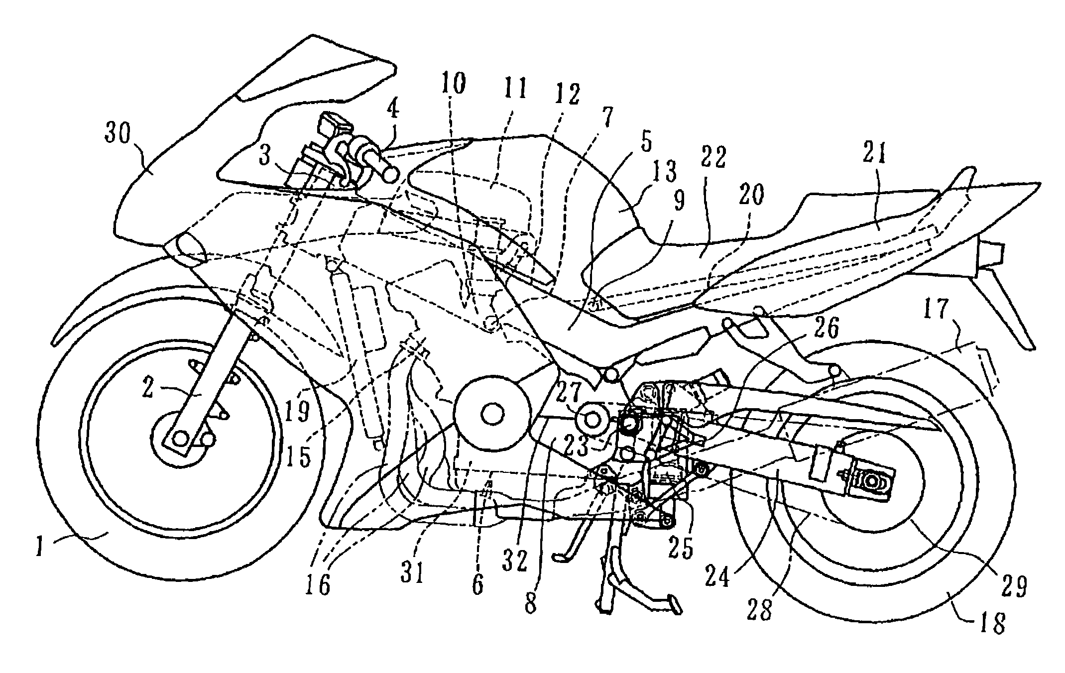
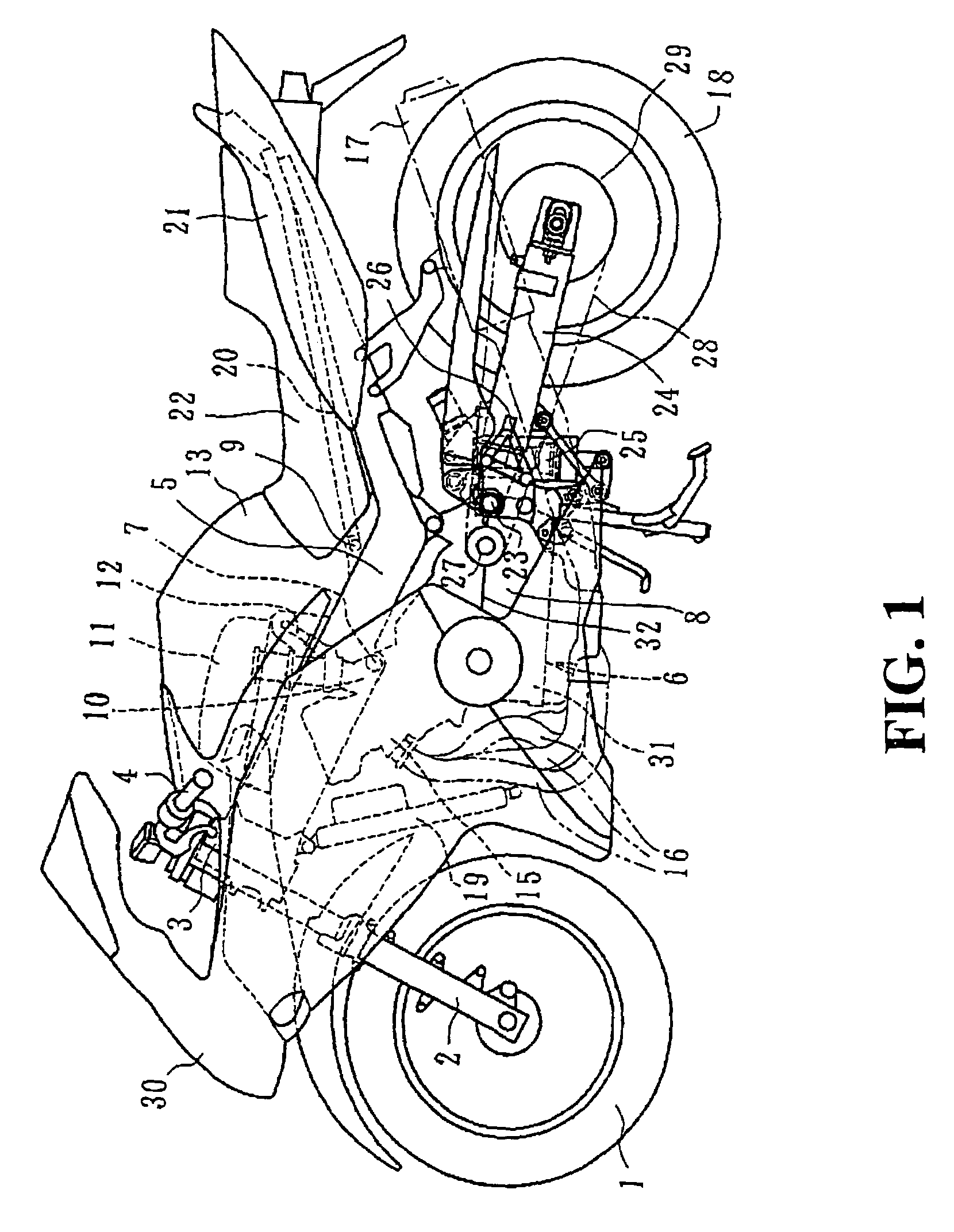
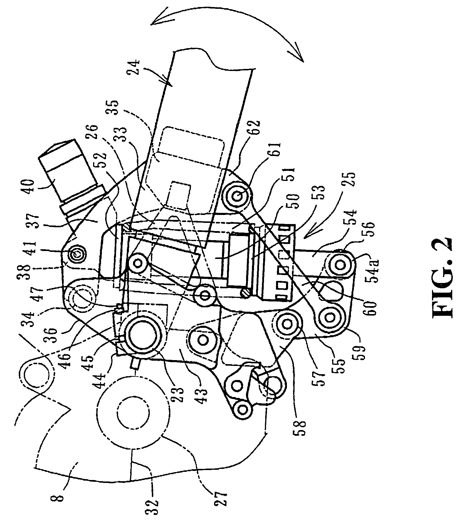
[0035]FIGS. 1 to 4 show an example in which the present invention has been applied to a supporting-at-both ends type rear swing arm, and FIG. 1 is a side view showing a motorcycle according to the present embodiment; FIG. 2 is a side view showing a rear suspension portion; FIG. 3 is its plan view; and FIG. 4 is a cross-sectional view showing a link mechanism.

[0036]FIG. 1 shows a front wheel 1; a front fork 2; a head pipe 3; a handlebar 4; and a main frame 5. The main frame 5 is shaped like a longitudinal square cylinder, made of light alloy, and branches off into left and right parts from the head pipe to extend obliquely downward toward the rear.

[0037]Below the main frame 5, there is supported a series four-cylinder engine 6. There are two supporting points: a coupling point 7 between the intermediate portion of the main frame 5 and the upper portion of the cylinder; and a coupling point 9 between the rear end of the main frame 5 and the upper portion of the a mission case 8 for co...


PUM


Abstract

A structure for installing a rear cushion in a motorcycle having a hydraulic shock absorber with a subsidiary cylinder used as the suspension device. The rear swing arm includes a pair of left and right arm portions, the respective front portions being coupled with a first cross member and a second cross member. A pair of cushion brackets extend in the back-and-forth direction with the upper portion of the rear cushion sandwiched therebetween. The front and rear ends of the cushion brackets are coupled to the first and second cross members, thereby supporting the cushion brackets at both ends. An upper portion of the rear cushion fits within a space enclosed by the first and the second cross members, and the left and right cushion brackets, and is coupled to the intermediate portion of the left and right cushion brackets.

Description


Claims


Application Information

Patent Timeline
Owner HONDA MOTOR CO LTD
Why Eureka
Try Eureka