Convergent turbojet exhaust nozzle

a turbojet and exhaust nozzle technology, applied in the direction of marine propulsion, vessel construction, aircraft navigation control, etc., can solve the problems of small radius of curvature in the join zone, reduce the amount of thrust provided in afterburner mode, and it is not satisfactory to equip the flaps of cmc material with metal portions at their ends, so as to reduce the wear caused by the flaps rubbing and limit wear

Active Publication Date: 2009-01-13
SN DETUDE & DE CONSTR DE MOTEURS DAVIATION S N E C M A
View PDF17 Cites 4 Cited by
  • Summary
  • Abstract
  • Description
  • Claims
  • Application Information

AI Technical Summary

Benefits of technology

[0006]A particular object of the invention is to provide a simple, low cost, and effective solution to this problem.
[0009]At its upstream end, each flap is also made integrally with hinge means pivotally connected to the upstream ends of the adjacent flaps. This makes it possible to reduce the leakage sections at the joins between the adjacent flaps, and therefore makes it possible to prevent or to reduce the leakage of afterburner gas at said joins.
[0010]Each of the controlled flaps and each of the follower flaps is thus made integrally as a single piece with its bearing means for bearing against the sealing gasket, its longitudinal sealing means, and its pivot hinge means. The number of parts used to make the convergent exhaust nozzle of the invention is therefore small. The flaps are made entirely out of ceramic-matrix composite material, thereby reducing the weight of the exhaust nozzle.
[0014]Longitudinal sealing between the hinged flaps is thus provided in simple manner by the flaps themselves. The convex curved shape of the longitudinal edges of the follower flaps makes it possible to limit wear caused by the flaps rubbing against one another, with rubbing taking place on the top layers of the follower flaps.
[0016]In order to further reduce wear caused by the flaps rubbing, said flaps may be coated at least part in an anti-abrasion coating at their upstream ends and along their longitudinal edges.

Problems solved by technology

However, mounting hot flaps of CMC material in a convergent exhaust nozzle of the above-mentioned type poses the problem of sealing between the flaps at the peripheral gasket arranged at the outlet from the afterburner channel: the flaps of CMC material are several times thicker than metal flaps, and as a result of their layered sheet structure, they cannot have a small radius of curvature in the join zones between adjacent flaps.
This results in relatively large leakage sections in the join zones through which afterburner gas can escape, thereby reducing the amount of thrust provided in afterburner mode.
In addition, it would not be satisfactory to equip the flaps of CMC material with metal portions at their ends that co-operate with the above-mentioned peripheral gasket because of the differential thermal expansion between the metal portions and the composite material.

Method used


Image

  • Convergent turbojet exhaust nozzle
  • Convergent turbojet exhaust nozzle
  • Convergent turbojet exhaust nozzle

Examples


Embodiment Construction

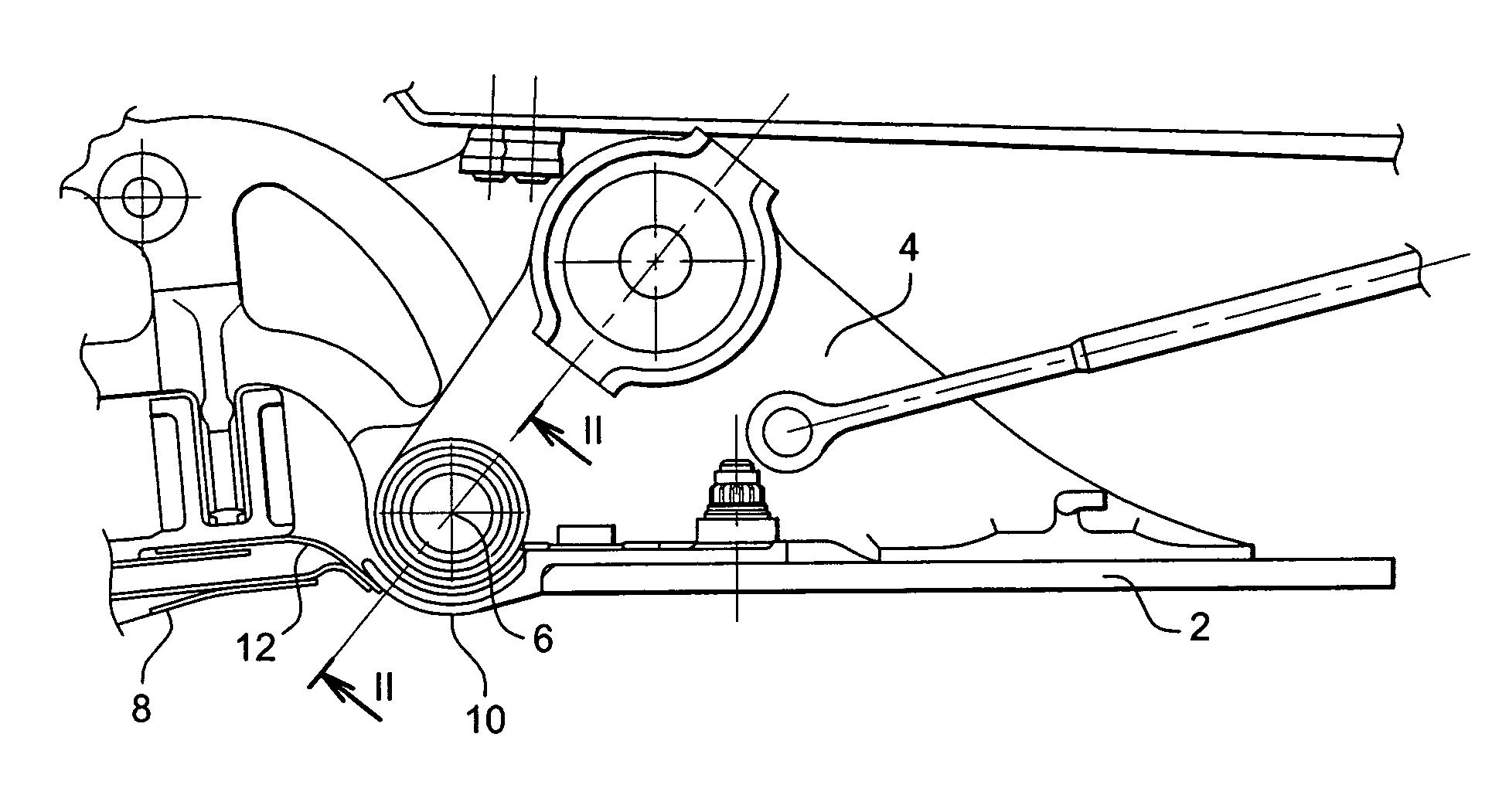
[0026]Reference is made firstly to FIG. 1 which is a diagrammatic side view showing a controlled flap of a convergent exhaust nozzle at the outlet from an afterburner channel of a turbojet.

[0027]The controlled flap 2 is carried by a support part 4 connected to drive means, so as to pivot about an axis 6 at its upstream end, at the outlet from the afterburner channel 8.

[0028]The upstream end 10 of the controlled flap 2 bears against a peripheral sealing gasket 12 of the sealing-lip type, so that the hot gas leaving the afterburner channel 8 flows inside the exhaust nozzle formed by the flaps.

[0029]In known manner, the flaps of the convergent exhaust nozzle arranged at the outlet from the afterburner channel 8 comprise controlled flaps 2 disposed in alternation with follower flaps that are not connected directly to drive means, but which follows the movement of the controlled flaps 2.

[0030]When the flaps are made of metal, the junctions between adjacent flaps at their upstream ends 10...


PUM


Abstract

A convergent turbojet exhaust nozzle comprising a ring of hinged flaps made up of controlled flaps and of follower flaps disposed in alternation and co-operating at their upstream ends with a peripheral sealing gasket arranged at the outlet from an afterburner channel, each flap being made out of a ceramic-matrix composite material, and at its upstream end, each flap being made integrally with bearing means for bearing against the above-mentioned peripheral gasket, and with spherical-joint means between their upstream ends.

Description

[0001]The present invention relates to a convergent turbojet exhaust nozzle formed at the outlet from an afterburner channel by a ring of hinged flaps comprising controlled flaps disposed in alternation with follower flaps.BACKGROUND OF THE INVENTION[0002]The flaps can occupy a position in which they substantially extend the wall of the afterburner channel, and a position in which they are inclined relative to the axis of the afterburner channel so as to increase thrust.[0003]The flaps, which are metal in the prior art, come into contact with the high-temperature gas leaving the afterburner of the turbojet, and as a result they have a relative short lifetime that could be increased by making the flaps out of a material that withstands high temperatures better, e.g. a ceramic-matrix composite material (CMC), which material would also reduce the weight of the flaps without substantially increasing their cost.[0004]However, mounting hot flaps of CMC material in a convergent exhaust noz...

Claims


Application Information

Patent Timeline
Patent Type & Authority Patents(United States)
IPC IPC(8): F02K1/00F02K1/12F02K1/80
CPCF02K1/12F02K1/1207F02K1/805Y02T50/672Y02T50/60
Inventor BLANCHARD, STEPHANE PIERRE GUILLAUMEARNOLD, THIBAULT MARIE-JACQUES
Owner SN DETUDE & DE CONSTR DE MOTEURS DAVIATION S N E C M A
Why Eureka
Try Eureka