Miniaturised half-wave balun

a half-wave balun and miniaturised technology, applied in the direction of waveguides, electrical devices, multiple-port networks, etc., can solve the problems of unsuitable applications, problems in circuitry, and large operating frequency of half-wave balun of fig. 1

Active Publication Date: 2009-01-20
TDK CORPARATION
View PDF11 Cites 31 Cited by
  • Summary
  • Abstract
  • Description
  • Claims
  • Application Information

AI Technical Summary

Problems solved by technology

However, it is sometimes more practical to realize a particular device in a single-ended topology (for example single-ended antennae are often preferred to balanced antennae).
The half-wave balun of FIG. 1 has the drawback of being very large at the operating frequencies of typical commercial cellular and W-LAN applications.
Consequently, the balun of FIG. 3 is unsuitable for applications where a high common mode signal level far outside the passband of the balun gives rise to problems in the circuitry to which the balun is connected.
Another drawback of the LC balun 30 of FIG. 3 is that it requires two inductors 34 and 36.
Unfortunately, if the circuit is to be fabricated using LTCC materials with a high dielectric constant, the realization of high Q inductors is difficult, and the insertion loss of the circuit becomes high.
A further drawback of the LC balun 30 of FIG. 3 is that a pair of bias-tee networks are required in order to apply a DC bias to signal carrying terminals T2 and T3 of I / O port P2.

Method used


Image

  • Miniaturised half-wave balun
  • Miniaturised half-wave balun
  • Miniaturised half-wave balun

Examples


first embodiment

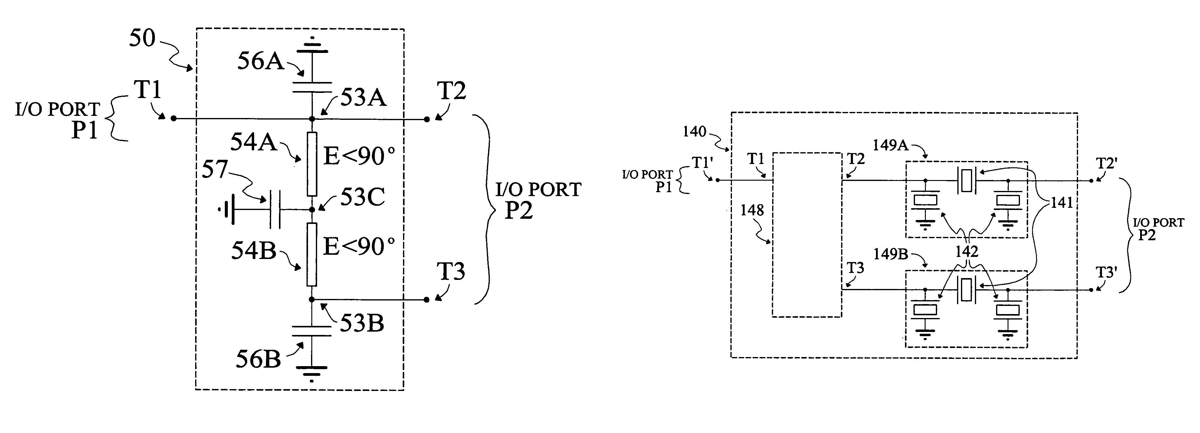
[0057]FIG. 5 shows a miniaturised half-wave balun 50 according to the present invention. The half-wave balun 50 has a given operating band defined by a lower frequency limit FL and an upper frequency limit FU. The half-wave balun 50 comprises a pair of transmission line sections 54A and 54B which have substantially identical physical properties and where each of transmission line sections 54A and 54B has an electrical length E which is substantially less than 90° at the centre of the operating band of the half-wave balun50. A first end of transmission line section 54A is connected to a shunt capacitor 56A at a first circuit node 53A, a first end of transmission line section 54B is connected to a shunt capacitor 56B at a second circuit node 53B, second ends of transmission line sections 54A and 54B are connected together at a third circuit node 53C, and a shunt capacitor 57 is also connected to third circuit node 53C.

[0058]The miniaturised half-wave balun 50 of FIG. 5 further compris...

second embodiment

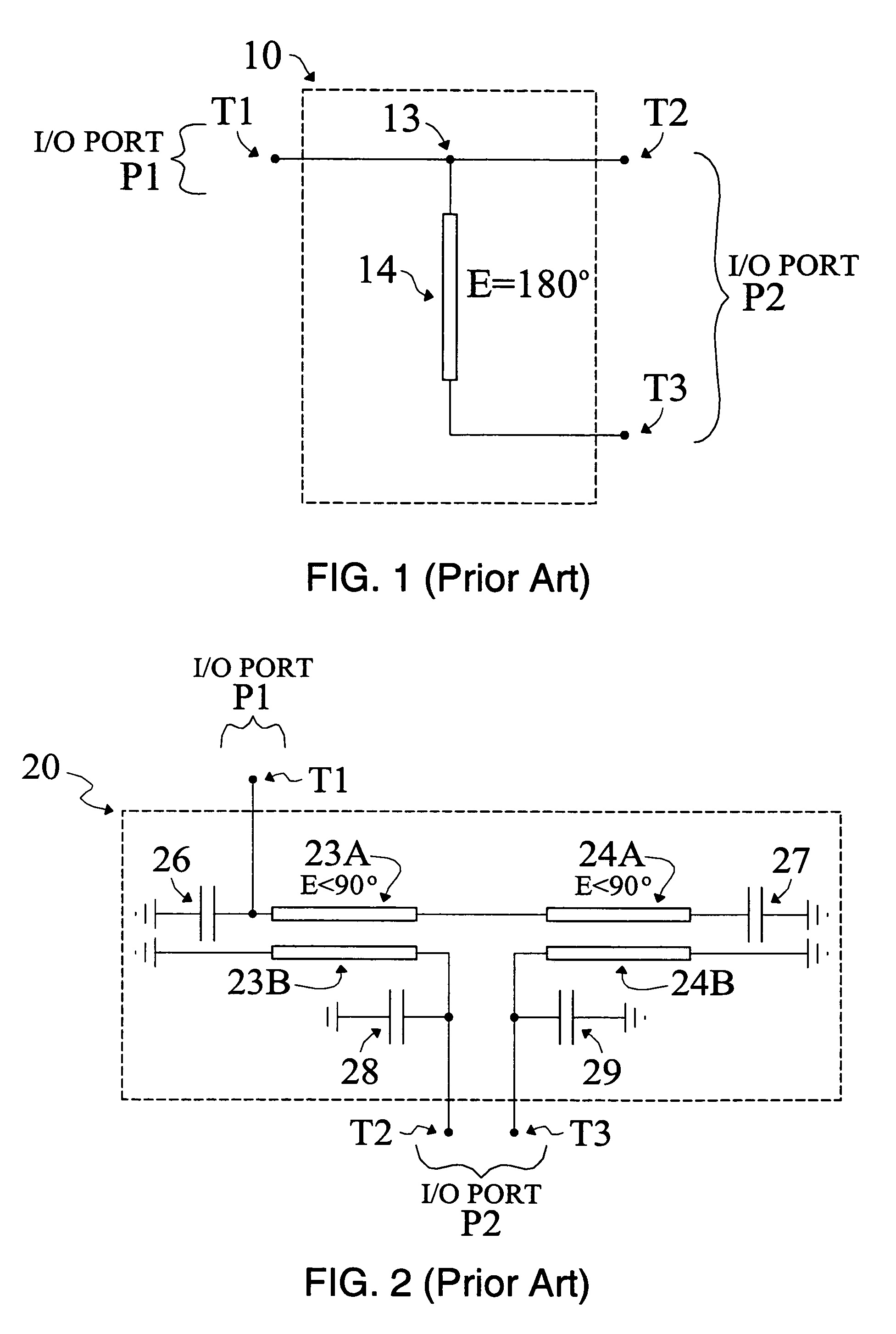
[0073]FIG. 7 shows a miniaturised half-wave balun 70 according to the present invention. The half-wave balun 70 having a given operating band defined by a lower frequency limit FL and an upper frequency limit FU.

[0074]The half-wave balun 70 comprises a pair of transmission line sections 74A and 74B which have substantially identical physical properties and where each of transmission line sections 74A and 74B has an electrical length E which is substantially less than 90° at the centre of the operating band of the half-wave balun 70. A first end of transmission line section 74A is connected to a shunt capacitor 76A at a first circuit node 73A, a first end of transmission line section 74B is connected to a shunt capacitor 76B at a circuit point 73B, second ends of transmission line sections 74A and 74B are connected together at a second circuit node 73C, and a shunt capacitor 77 is also connected to second circuit node 73C.

[0075]The miniaturised half-wave balun 70 of FIG. 7 further co...

third embodiment

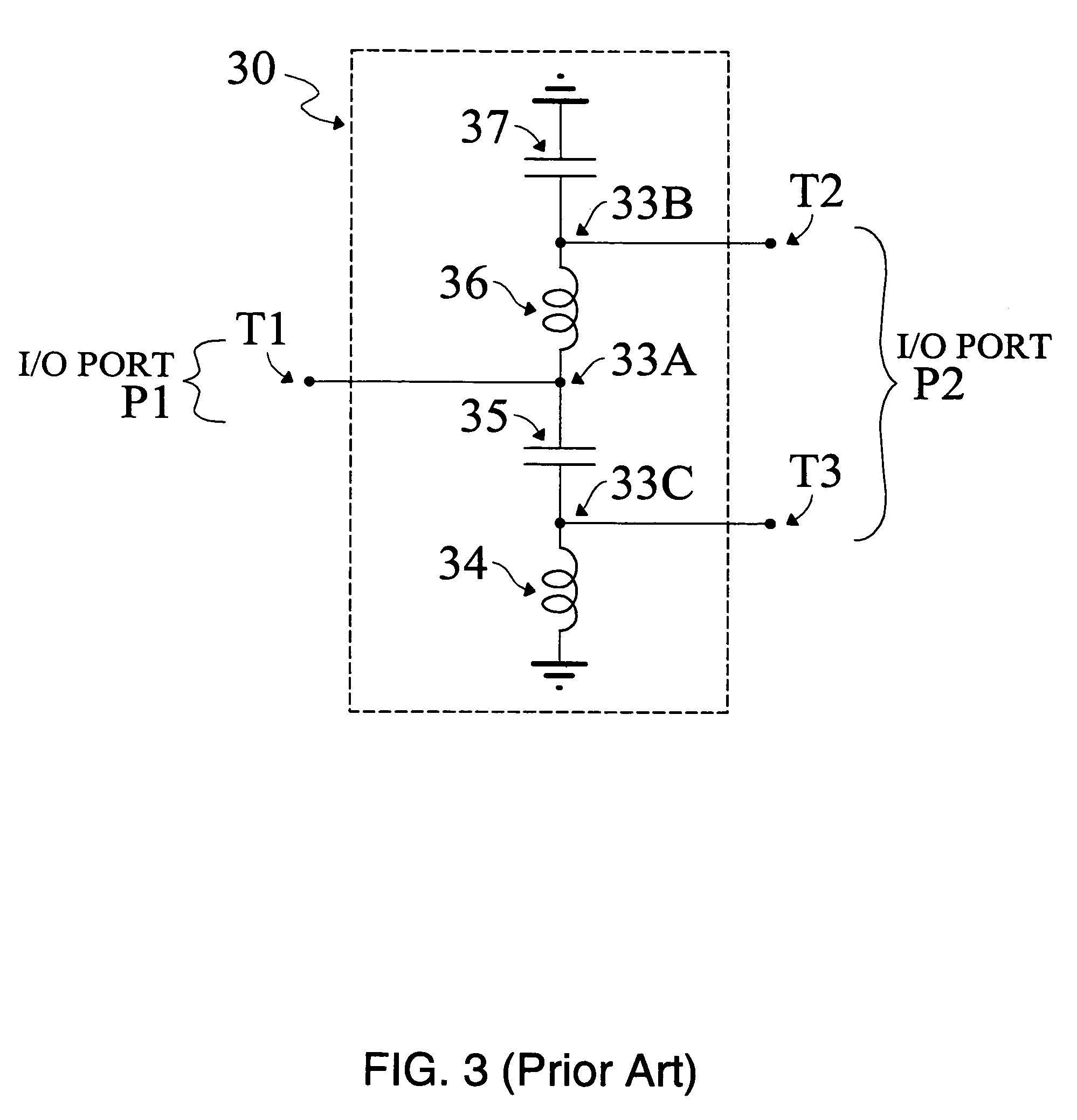
[0081]FIG. 9A shows a miniaturised coupled-line half-wave balun 90 according to the present invention. The coupled-line half-wave balun 90 having a given operating band defined by a lower frequency limit FL and an upper frequency limit FU.

[0082]The coupled-line half-wave balun 90 of FIG. 9A comprises a first pair of coupled transmission line sections comprising coupled transmission line sections 93A and 93B and a second pair of coupled transmission line sections comprising coupled transmission line sections 94A and 94B, where the first pair of coupled transmission line sections 93A and 93B has substantially the same physical properties as the second pair of coupled transmission line sections 94A and 94B, and where the electrical length E of each of coupled transmission line sections 93A, 93B and 94A, 94B is substantially less than 90° at the centre of the operating band of the coupled-line half-wave balun 90.

[0083]A first end of coupled transmission line section 93A is connected to ...


PUM


Abstract

A miniaturised half-wave balun comprises a single-ended I / O port comprising a first signal carrying terminal for connection to a source impedance and a differential I / O port comprising second and third signal carrying terminals for connection to a load impedance. First and second transmission line sections of equal length and characteristic impedance are connected together at a common end and at opposite ends to the second and third terminals. The first signal carrying terminal is coupled to the first transmission line section. The combined length of the first and second transmission line sections is substantially less than one half of the wavelength of an RF signal at the operating frequency. First and second loading shunt capacitors are connected to respective first and second transmission line sections. A shunt capacitive element is connected at the common end of the transmission line sections. The capacitance of the shunt capacitive element is chosen so that the common mode impedance of said differential I / O port at a selected frequency is substantially zero Ohms.

Description

CROSS-REFERENCES[0001]The present application is related to co-filed application Ser. No. 11 / 397,859 entitled “A Compact RF Circuit with High Common Mode Attenuation”.FIELD OF THE INVENTION[0002]This invention relates to a miniaturised half-wave balun useful in the field of radio frequency (RF) devices, RF components and RF circuits, particularly where conversion of single-ended RF signals to differential RF signals or conversion of differential RF signals to single-ended RF signals is required.BACKGROUND OF THE INVENTION[0003]Conventional electronic circuits for RF and telecommunications applications comprise one or more input ports to which input RF signals of the electronic circuit are fed, and one or more output ports from which output RF signals of the electronic circuit are emitted. Single-ended input / output ports have a pair of connection terminals: a signal terminal and a ground terminal, where the input and output RF signals of the electronic circuit are carried on the sign...

Claims


Application Information

Patent Timeline
Patent Type & Authority Patents(United States)
IPC IPC(8): H01P5/10H03H5/00H03H7/38H03H9/58
CPCH01P5/10
Inventor KEARNS, BRIANVERNER, WILLIAM
Owner TDK CORPARATION
Why Eureka
Try Eureka