Low profile automotive fuse

a low-profile, fuse technology, applied in the direction of basic electric elements, emergency protective devices, electrical equipment, etc., can solve the problems of less effective staking or attachment process, more cumbersome insertion and removal, and difficulty in removing the fuse block, so as to improve the fuse and improve the effect of low profil

Active Publication Date: 2009-01-20
LITTELFUSE INC
View PDF138 Cites 9 Cited by
  • Summary
  • Abstract
  • Description
  • Claims
  • Application Information

AI Technical Summary

Benefits of technology

[0028]It is another advantage of the present invention to provide an improved method of making a fuse.
[0029]Moreover, it is an advantage of the present invention to provide a “low profile” type of fuse, in which the insulative housing is securely fastened to the metal portion without requiring staking.
[0030]It is a further advantage of the present invention to eliminate additional insulative material with respect to known “low profile” fuses.
[0031]Furthermore, it is an advantage of the present invention to provide an apparatus that secures the terminal portion of the fuse within the insulative housing in multiple translational directions and about multiple axes of rotation.
[0032]Still further, it is an advantage of the present invention to secure the terminal portion of the fuse within the insulative housing so that the terminal portion is at least substantially centered within the housing.
[0033]Additional features and advantages of the present invention are described in, and will be apparent from, the following

Problems solved by technology

In certain instances if the housing is not properly attached to the terminals, the housing upon a short circuit can come free from the terminals or otherwise become difficult to remove from the fuse block.
The “low profile” fuse, while reducing the amount of metal and insulating material for a given rating, makes insertion and removal more cumbersome because there is less material exposed to grasp.
Further, the reduced metal and insulative material reduces the area of overlap between the metal and the insulative material, making the staking or attachment process more difficult and less effective.
The housings of known “low profile” fuses may therefore be more susceptible to dislodgement upon opening, creating a situation in which it is difficult to remove the male terminals of the fuse, which are friction fitted to the female terminals of the fuse block.

Method used


Image

  • Low profile automotive fuse
  • Low profile automotive fuse
  • Low profile automotive fuse

Examples


Embodiment Construction

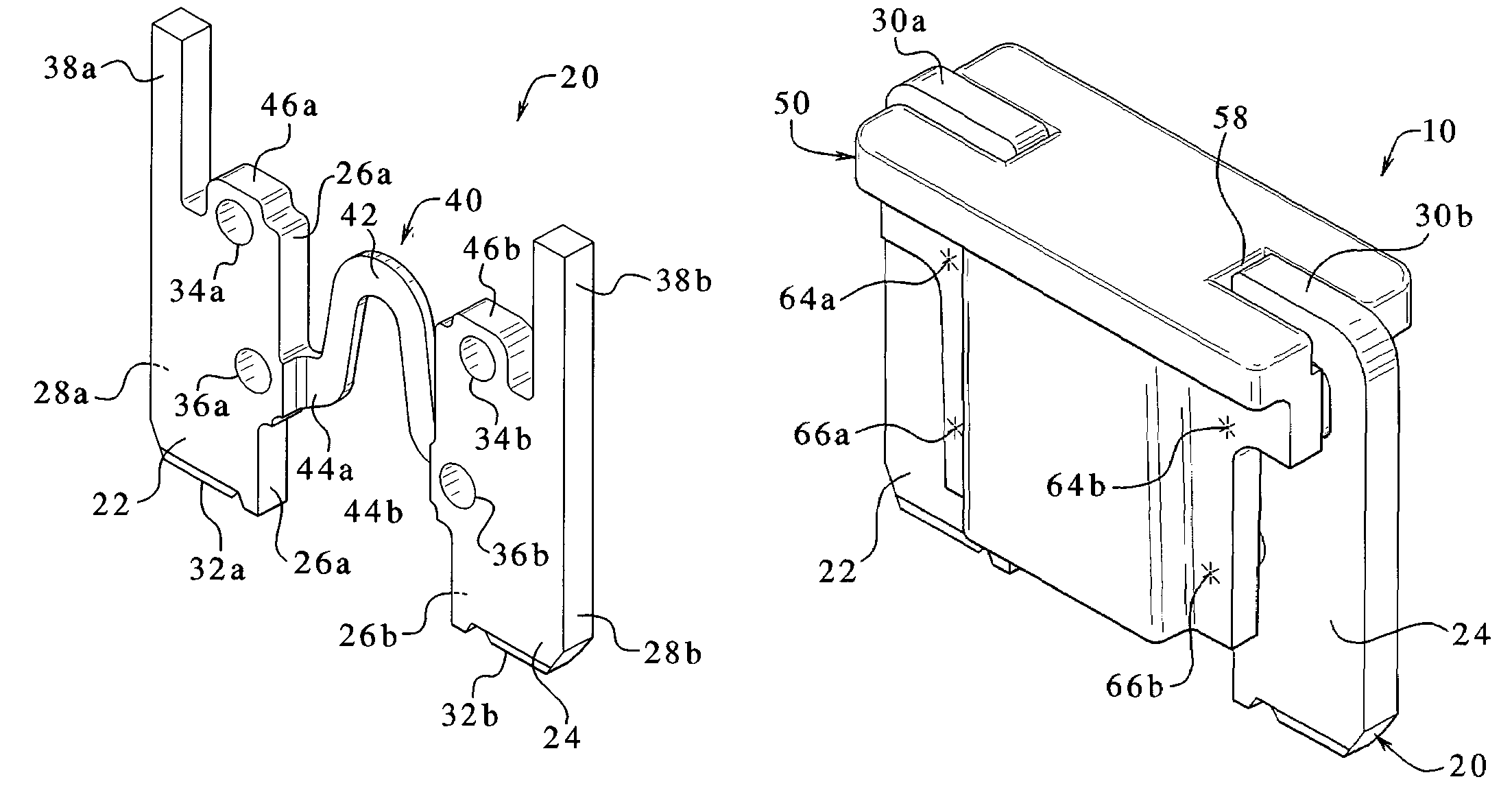
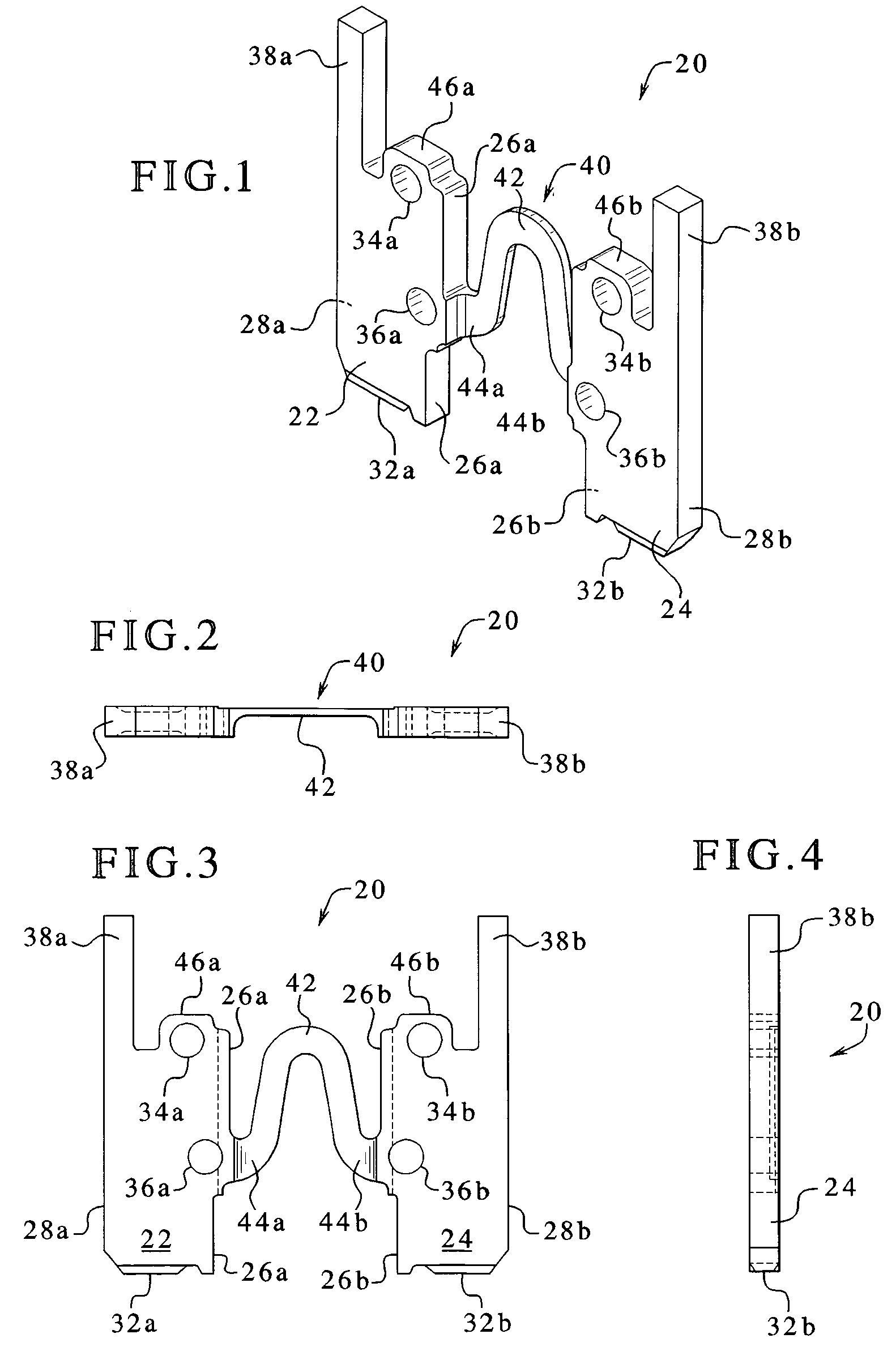
[0038]Referring now to FIGS. 1 to 12, one embodiment of a fuse 10 of the present invention is illustrated. Fuse 10 includes a conductive or metal portion 20 and an insulative housing 50. Conductive or metal portion 20 can be made of any suitable conductive material, such as metal. In various embodiments, conductive portion 20 is made of copper, aluminum, zinc, nickel, tin, gold, silver and any alloys or combinations thereof. In alternative embodiments, the conductive portion 20 or sections thereof can be plated with one or more metal or conductive plating.

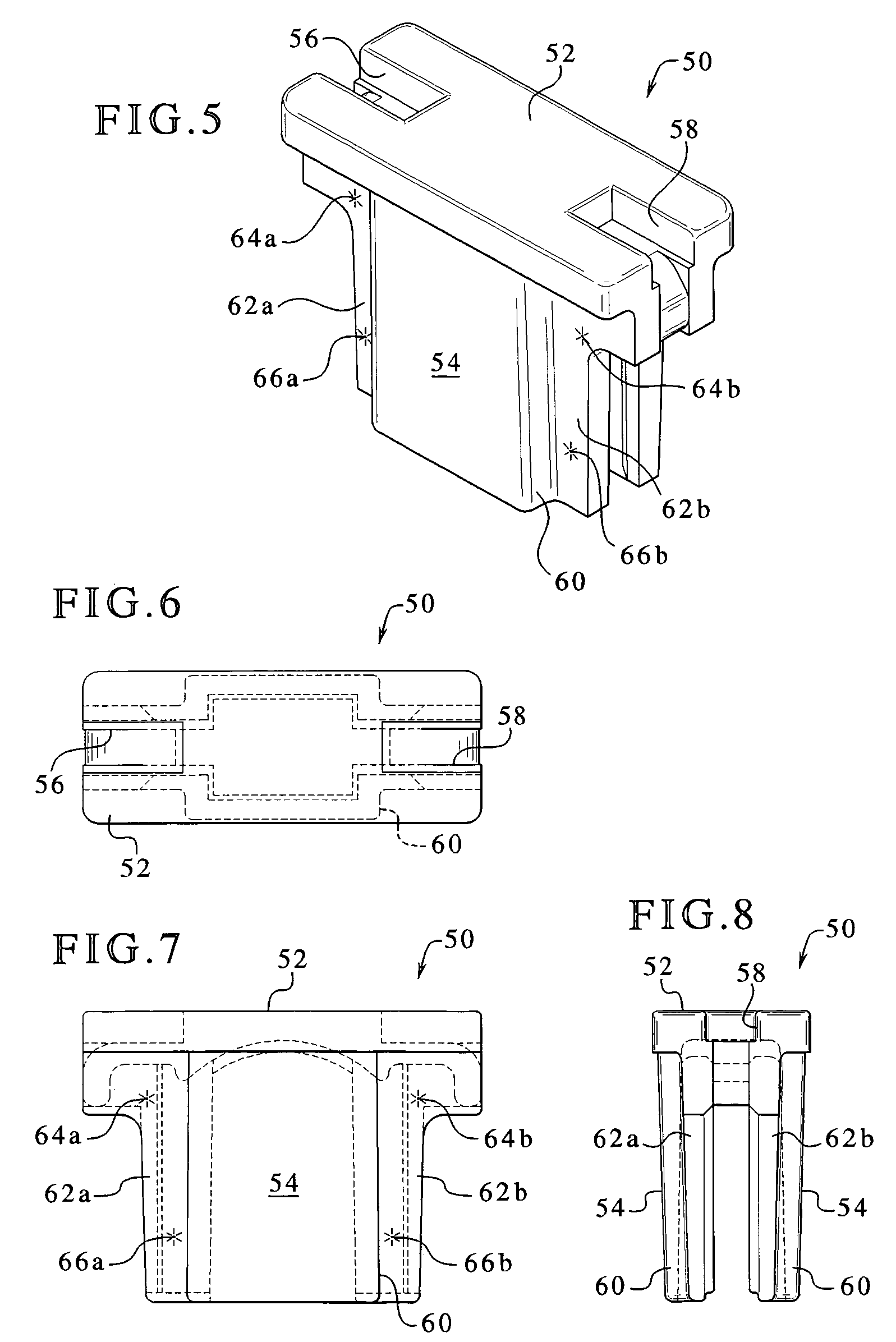
[0039]Insulative housing 50 is made of any suitable plastic or non-conductive material. For example, housing 50 can be made of any of the following materials: polycarbonate, polyester, polyethylene, polypropylene, polystyrene, polyvinylchloride, polyvinylidene chloride, acrylic, nylon, phenolic, polysulfone and any combination or derivative thereof. In one embodiment, conductive portion 20 is stamped, wire electrical discharge mach...


PUM


Abstract

An automotive blade-type fuse and method of manufacturing same are provided. The fuse includes a pair of metallic terminals separated by and in electrical communication with a fuse element. An insulative housing is provided that covers at least a portion of an inner edge of each of the terminals and exposes the outer edges of the terminals and at least a portion of the upper edges of the terminals. The terminals can define grooves that interface with projections extending inwardly from the housing to hold the terminals firmly within the housing. Also, the upper edges of the terminals are bent inward to crimp the housing between an intermediate portion of the terminals and the bent upper end edges.

Description

PRIORITY CLAIM[0001]This application claims priority to and the benefit of U.S. Provisional Patent Application “LOW PROFILE AUTOMOTIVE FUSE,” Ser. No. 60 / 550,682, Filed Mar. 5, 2004.BACKGROUND OF THE INVENTION[0002]The present invention relates to fuses and more particularly to automotive fuses.[0003]Automotive fuses, such as blade type fuses are known in the art. Modern electrical blade fuses have been manufactured by Littelfuse, Inc., the assignee of the present invention. Blade fuses protect electrical automotive circuits from current overloads. The protection results from the creation of an opening of a fuse element of the fuse, and therefore in the circuit protected by the fuse. Upon a current overload of a certain magnitude and over a predetermined length of time the fuse element or link breaks or opens.[0004]Blade fuses are used extensively in automobiles. Automobile manufacturers are constantly looking for ways to reduce costs as much as possible. Manufacturers strive to red...

Claims


Application Information

Patent Timeline
Patent Type & Authority Patents(United States)
IPC IPC(8): H01H85/165H01H85/044H01H85/02H01H85/041
CPCH01H85/0417H01H85/165
Inventor GOLDSBERRY, TIMOTHY R.HARRIS, EDWIN JAY
Owner LITTELFUSE INC
Why Eureka
Try Eureka