Fluid flow control device

a flow control and flow rate technology, applied in the direction of process and machine control, lighting and heating apparatus, instruments, etc., can solve the problems of high cost, difficult reliability, complex construction, etc., and achieve the effect of constant flow rate and less manufacturing cos

Inactive Publication Date: 2009-01-27
BIOQ PHARMA
View PDF11 Cites 15 Cited by
  • Summary
  • Abstract
  • Description
  • Claims
  • Application Information

AI Technical Summary

Benefits of technology

[0011]It is an object of the invention to provide a flow control device of simple construction that reliably delivers a substantially constant output flow rate under conditions of fluctuating or otherwise varying temperature and pressure.
[0018]Another object of the invention is to provide a flow control device of the type described in the preceding paragraphs which can be manufactured less expensively than conventional prior art flow control devices.

Problems solved by technology

Such constructions tend to be complex, costly and often of questionable reliability, particularly when used in medical applications.

Method used


Image

  • Fluid flow control device
  • Fluid flow control device
  • Fluid flow control device

Examples


Embodiment Construction

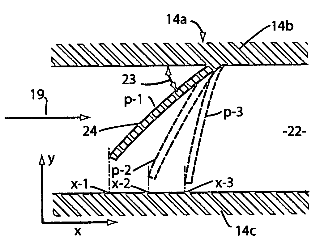
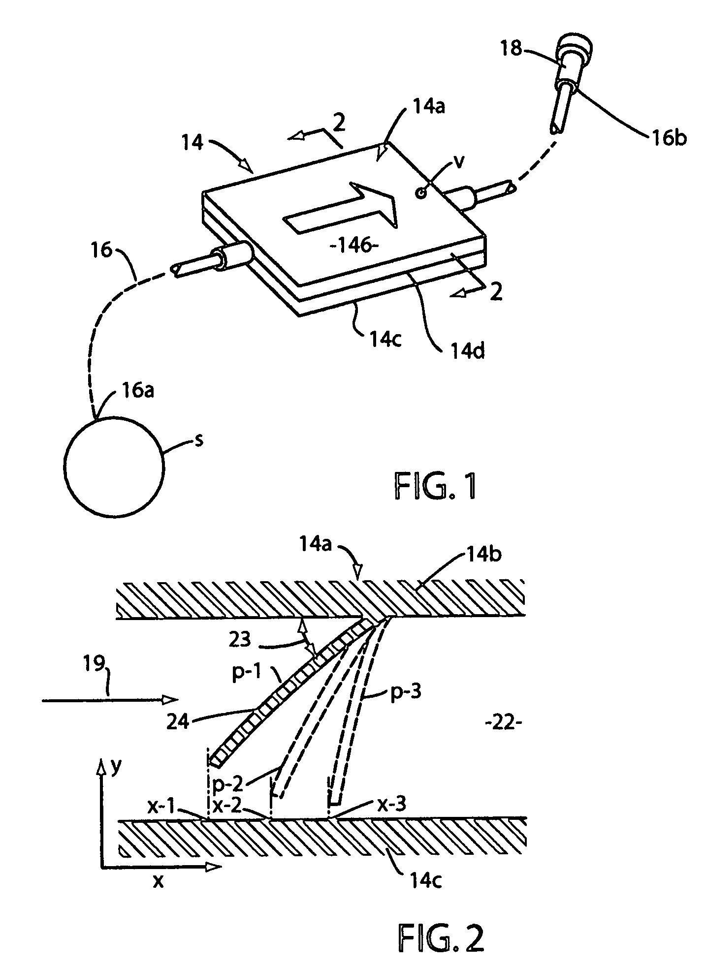
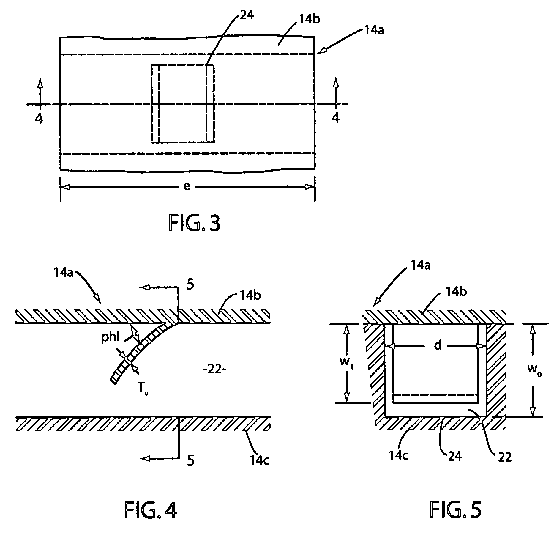
[0050]As previously discussed, it is a primary object of the present invention to provide a device that includes novel means for occluding a flow channel in a flow control device in such a way that, as the pressure of the fluidic system is increased, the relative degree of occlusion of the fluid pathway is also increased and as the temperature of the system is decreased the relative degree of occlusion is decreased. Thus, the design of a device that delivers fluid at a flow rate independent of pressure will likely require substantial changes in the micro-fluidic system. To a good approximation in the case of simple laminar flow, the flow rate is directly proportional to the pressure, assuming all other variables are held constant. For example, if the pressure increases by a factor of two, then the flow rate will be increased to twice its original value. Part of the challenge faced by the present inventor was to design a device that can achieve this objective without the use of elect...


PUM


Abstract

A flow control device of the character having a fluid pathway for permitting fluid flow therealong under conditions of varying temperature and pressure for achieving substantially constant output flow rate from the fluid pathway. One or more flexibly deformable vanes, which extend into the fluid pathway, are constructed and arranged to flexibly deform in a manner to further occlude the fluid pathway when the pressure within said fluid path way increases.

Description

[0001]This is a Non-Provisional Application claiming the benefit of co-pending Provisional Application No. 60 / 811,228 filed Jun. 5, 2006.BACKGROUND OF THE INVENTION[0002]1. Field of the Invention[0003]The present invention relates generally to fluid flow control devices for controlling the flow of fluid along fluid flow pathways. More particularly, the invention concerns a highly novel fluid flow control device that delivers a substantially constant output flow rate from a micro-fluidic system under conditions of fluctuating or otherwise varying temperature and pressure by lining the fluid flow pathway with vanes, weirs, fibers or whiskers that move further into the channel as the pressure of the fluid flowing through the fluid flow pathway increases.[0004]2. Discussion of the Prior Art[0005]Various types of fluid flow control devices have been suggested in the past. Typically, these prior art devices use flow regulators, valves, diaphragms and like constructions all employing movin...

Claims


Application Information

Patent Timeline
Patent Type & Authority Patents(United States)
IPC IPC(8): F15D1/00
CPCG05D7/012G05D7/0173
Inventor BIVIN, DONALD B.
Owner BIOQ PHARMA
Why Eureka
Try Eureka