Cutter apparatus

a cutting machine and cutting blade technology, applied in the field of plant cutting system, can solve the problems of large damage to plants and trellises, high maintenance cost, safety concerns, etc., and achieve the effect of reducing the chance of striking objects and small diameter

Inactive Publication Date: 2006-07-27
OXBO INT CORP
View PDF10 Cites 32 Cited by
  • Summary
  • Abstract
  • Description
  • Claims
  • Application Information

AI Technical Summary

Benefits of technology

[0010] An opener wheel is disposed within the stack of cutter assemblies to engage objects such as trellis posts and avoid damage to the cutter assembly. The opener wheel typically has a diameter slightly larger than the outermost diameter of the guards or cutter members. With this arrangement, the opener wheels engage the post or other stationary object to cause the cutting assemblies to deflect and/or cause to open, rather than the cutters striking objects. The cutting assemblies follow around trellis posts as the opener wheel engages the post to maintain the cutters away from engagement.
[0011] The first cutting assemblies also include a lower rotary cutter assembly. The lower cutter assembly includes a stationary cutter section and complementary rotating cutter section that work together to create a shearing action. The lower rotary cutters provide a precision cut that becomes a desirable finish cut over the r

Problems solved by technology

However, safety, wear and damage to plants and trellises are a concern.
Some devices utilize high speed rotating saw blades, which may pose a safety concern and are expensive to maintain.
Other devices utilize rotating guards, which may reduce costs for blade replacement, but may also have an irregular or unsatisfactory cu

Method used


Image

  • Cutter apparatus
  • Cutter apparatus
  • Cutter apparatus

Examples


first embodiment

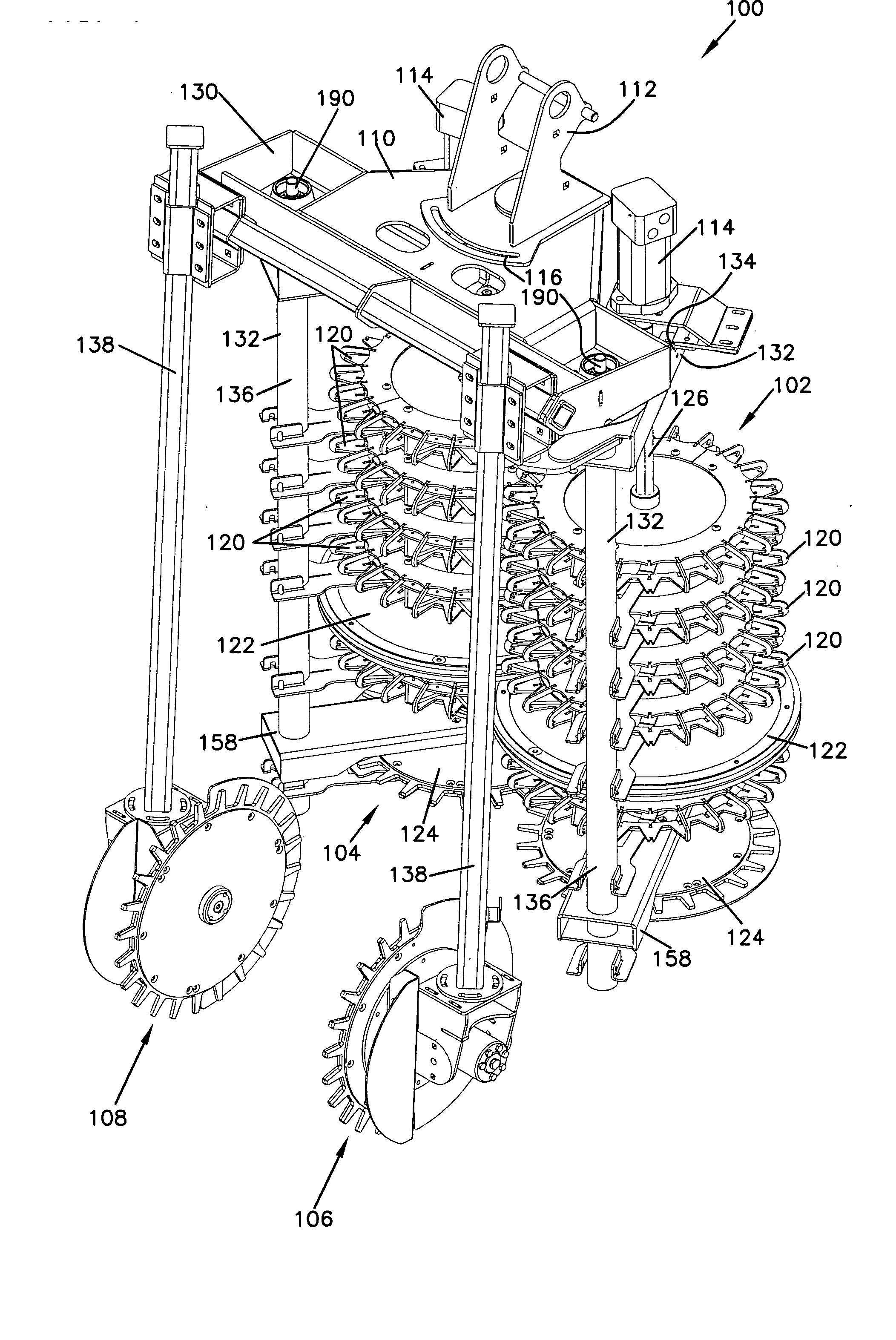
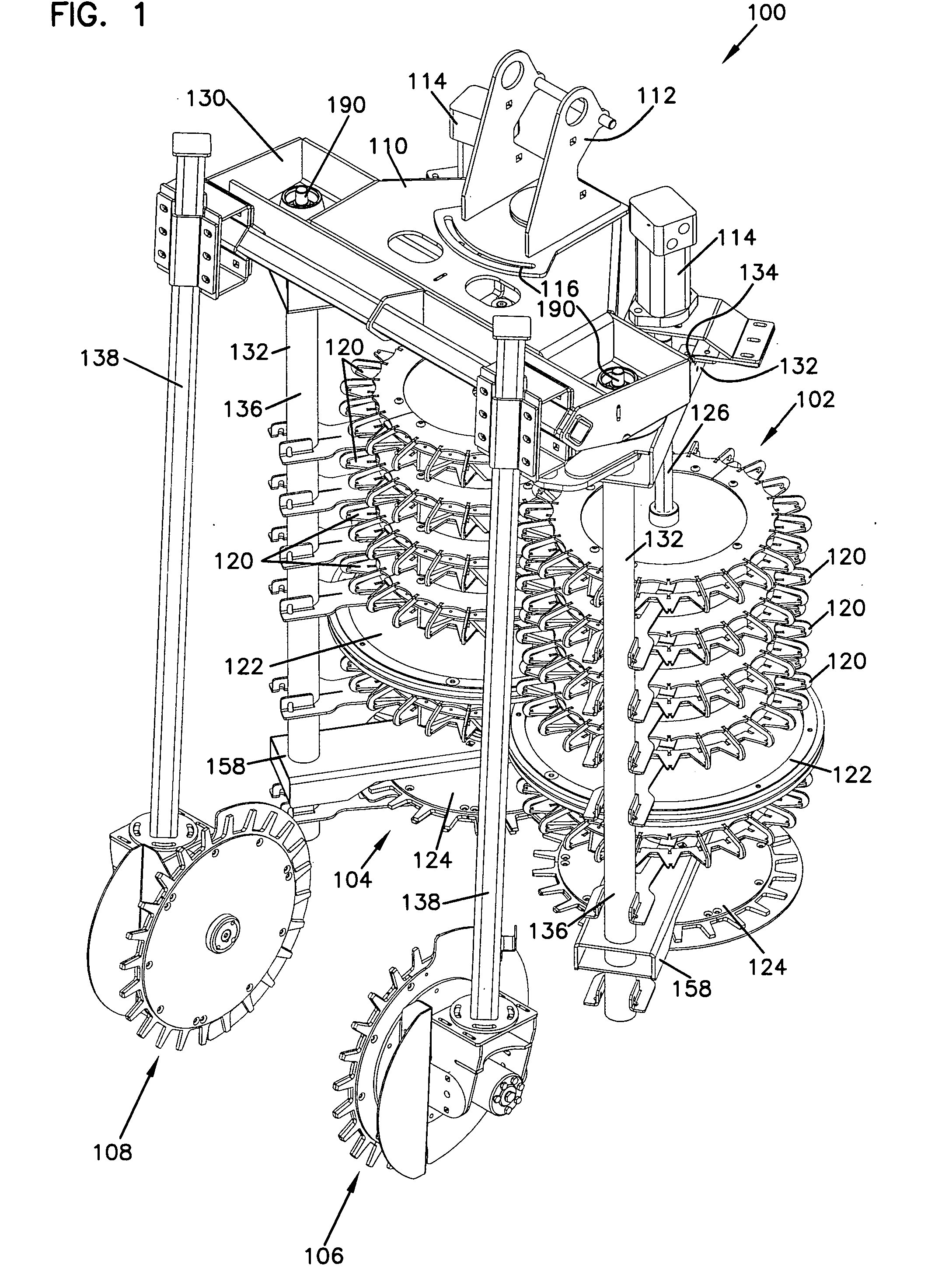
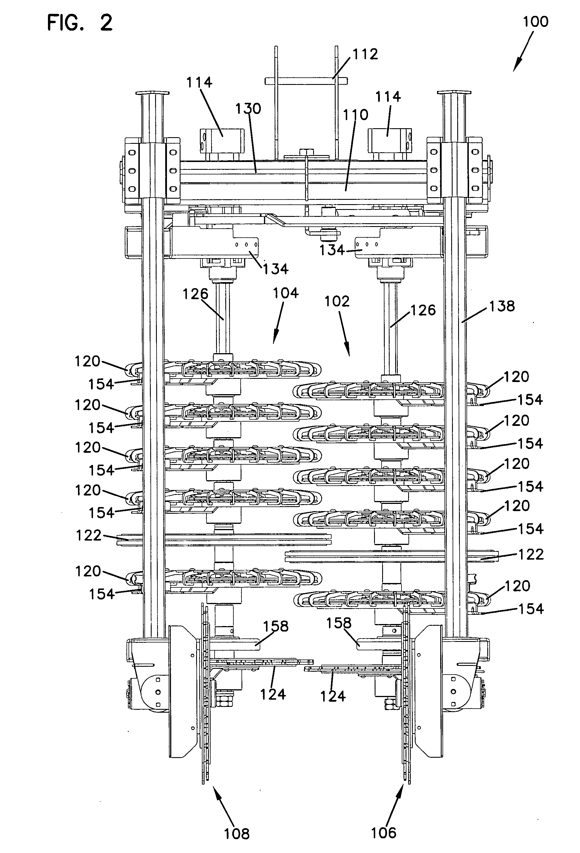
[0043] Referring now to the drawings, and in particular to FIGS. 1-7, there is shown a cutting system, generally designated 100, configured for cutting away portions of plants, such as grapes trained on trellises in vineyards. The cutting system 100 includes first cutting assemblies 102 and 104. Although one of the cutting assemblies 102 and 104 may be shown or described hereinafter, the cutting assemblies 102 and 104 are substantially the same except for being configured for cutting on the left portion or right portion of the system 100. In a first embodiment, the cutting system 100 also includes second cutting assemblies 106 and 108, which are also substantially the same as one another, but are configured for the left or right sides of the cutting system 100.

[0044] The cutting system 100 is configured for being supported on a frame 110 from above on a hanging mount 112. The hanging mount 112 includes an adjustment bracket 116 to vary the system position as needed. The mount 112 ma...

second embodiment

[0057] Referring now to FIGS. 20-23, there is shown second cutter assemblies, generally designated 306 and 308. Each of the second cutting assemblies 306 and 308 is mounted on an upper frame 310 including a mounting bar 312. Each of the cutting assemblies includes a mounting bracket 314 that clamps to the mounting bar 312. The lateral position of each of the cutting assemblies 306 and 308 may be varied by changing the mounting location on the bar 312. A hydraulic motor 316 powers each of the cutting assemblies 306 and 308. A sickle bar 320 includes a vertical support 322 and a reciprocating sickle blade 324. The sickle bar assembly 320 reciprocates in a back and forth, up and down motion to provide a precise side cut and cooperates with the first cutting assemblies 102 and 104 to form a box shaped profile. It can be appreciated that the sickle bar assemblies 306 and 308 provide for variable spacing as the sickle bar assemblies 306 and 308 are moved on the mounting bar 312. Moreover,...


PUM


Abstract

A cutting system for plants includes opposed first cutting assemblies and opposed second cutting assemblies. The first cutting assemblies include a substantially vertical stack of cage type cutters and a lower cutter having stationary and rotating cutter members. The cage type cutters include an outer driven guard that moves the plants past the stationary cutters. Opener wheels have a diameter slightly greater than the cutters and engage posts and other objects to position the cutting assemblies and to prevent damage to the cutting assemblies and trellises. Side cutter assemblies are positioned forward of the vertical stack of first cutting assemblies and provide precision side cuts. The side cutters include stationary cutter members and rotating cutter members that provide a precise shearing action. The system rotational speed is controlled to maintain a speed proportional to the ground speed so that a substantially constant percentage of plant material is removed.

Description

BACKGROUND OF THE INVENTION [0001] 1. Field of the Invention [0002] The present invention relates to a plant cutting system, and more particularly to a cutter system utilized for dormant pruning in vineyards and similar applications. [0003] 2. Description of the Prior Art [0004] Devices for performing pruning and thinning operations in vineyards have recently become more widely used. Such devices are used throughout various stages of the growing cycle to remove excess portions of the plant to control yield, maintain plant structure and increase fruit exposure. By removing the excess and / or aged portions of plant material, the plant, such as a grapevine, is able to focus more resources on the fruit so that quality is improved while attaining a desired yield. Although such operations have historically been performed by hand, the need for more efficient ways of performing such tasks has increased to improve the efficiency and economics of the vineyard. [0005] To reduce or eliminate som...

Claims


Application Information

Patent Timeline
IPC IPC(8): A01D34/73
CPCA01G17/02A01G3/0408
Inventor SCHLOESSER, CHRISTOPHER M.
Owner OXBO INT CORP
Why Eureka
Try Eureka