Multi-beam transmitting/receiving apparatus and transmitting/receiving method

a multi-beam transmitting/receiving and multi-beam technology, applied in the field of multi-beam transmitting/receiving apparatus and methods, can solve the problems of inoptimized transmission, prone to interference by another user, and insufficient beam direction for transmitting data, etc., to achieve simple arrangement and increase the accuracy of direction

Inactive Publication Date: 2009-01-27
NEC CORP
View PDF13 Cites 16 Cited by
  • Summary
  • Abstract
  • Description
  • Claims
  • Application Information

AI Technical Summary

Benefits of technology

[0022]It is an object of the present invention to provide a multibeam transmitting / receiving apparatus and transmitting / receiving method which are capable of increasing the accuracy of the direction in which to transmit a transmission beam with a simple arrangement, even if a user who is to transmit data is positioned near a point of intersection between two adjacent beams.
[0030]According to the present invention, therefore, a transmission beam is not formed in the same directivity pattern as a reception beam prepared in advance, but a transmission beam which is higher in accuracy than a reception beam is formed, so that a transmission antenna weight for transmitting data in the direction of a mobile station of a party to communicate with as a desired user can be generated with utmost ease. Therefore, data can be optimally transmitted to the desired user irrespective of the position where the user is present, and interference with other users which occurs if the peak direction of the beam is not optimum is reduced.

Problems solved by technology

However, CDMA has a problem in that a base station receiver tends to suffer interference from another user's signal which is making simultaneous access with the same carrier, and a mobile station receiver is liable to cause interference due to a signal set to another user.
However, the conventional multi-beam transmitting / receiving apparatus suffers the following problems: Even if the beam of a finger having the maximum signal power level is selected using the signal power levels measured by signal power measuring units 8-1 through 8-L and the beam numbers indicated by reception multibeam controller 13, and a downlink transmission is performed using the selected beam, the transmission is not optimized.
The reasons for the problem are as follows: If the user who is to transmit data is positioned near a point of intersection between two adjacent beams, then when one of the beams is selected and the data is transmitted with the selected beam, since the user is present in a position displaced off the peak direction of the beam, the direction of the beam for transmitting the data is not optimum, and the transmission tends to given interference to another user who is present in the peak direction of the beam.
However, the solution is not practical as the amount of calculations required for searcher 12 to generate delay profiles is increased.

Method used


Image

  • Multi-beam transmitting/receiving apparatus and transmitting/receiving method
  • Multi-beam transmitting/receiving apparatus and transmitting/receiving method
  • Multi-beam transmitting/receiving apparatus and transmitting/receiving method

Examples


1st embodiment

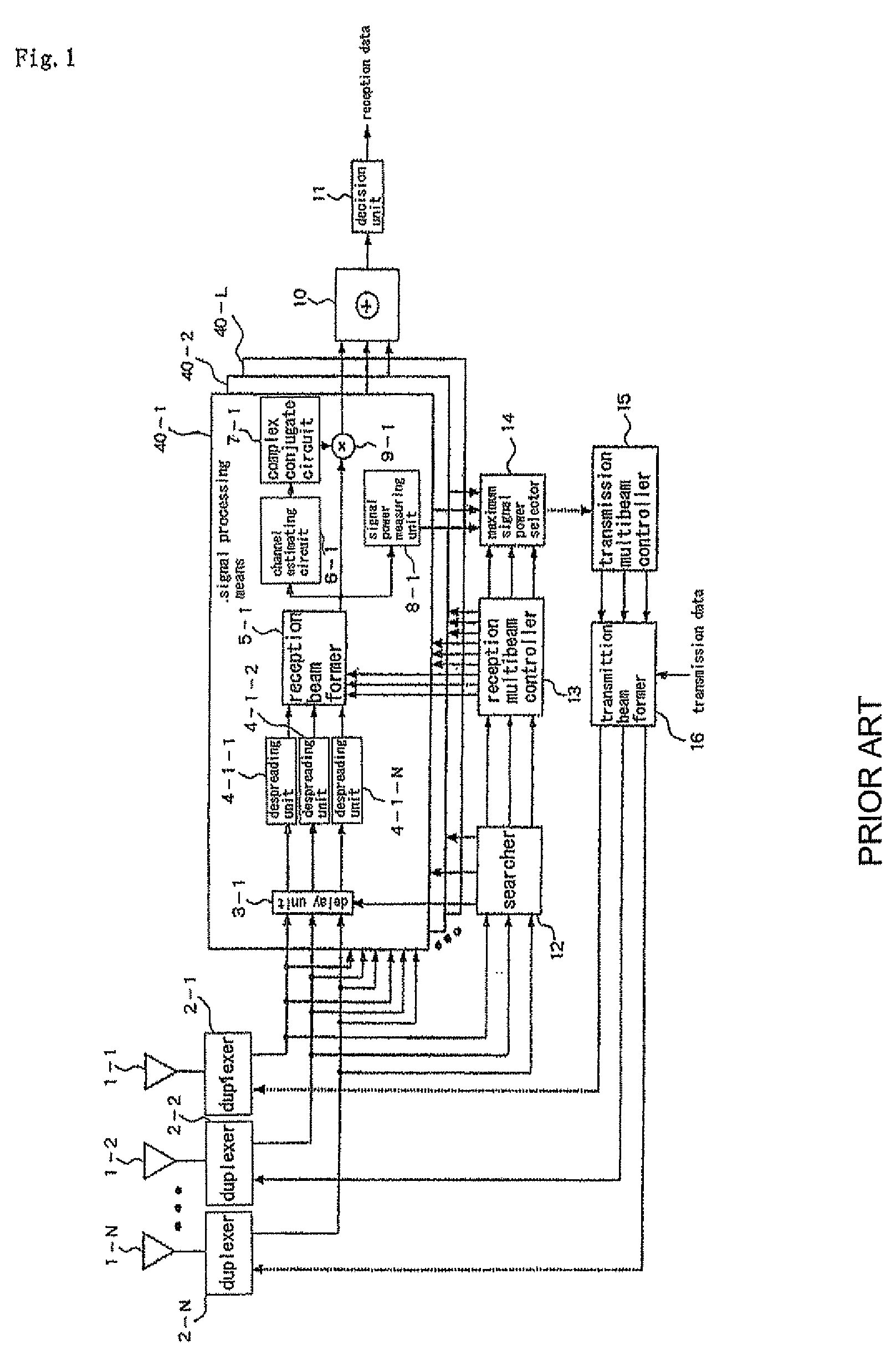
[0049]A first embodiment of the present invention will first be described in detail below with reference to the drawings. FIG. 6 is a diagram showing an arrangement of a multi-beam transmitting / receiving apparatus according to the first embodiment of the present invention. Those parts of the multi-beam transmitting / receiving apparatus which are identical to those shown in FIG. 1 are denoted by identical reference characters. It is assumed in FIG. 6 that the number of antennas is N, N being an integer of 2 or greater, the number of multipaths is L, L being an integer of 1 or greater, and the multi-beam transmitting / receiving apparatus is assigned to a kth user, k being an integer of 1 or greater.

[0050]As shown in FIG. 6, the multi-beam transmitting / receiving apparatus according to the present embodiment, which is assigned to the kth user, comprises N antennas 1-1 through 1-N, duplexers 2-1 through 2-N, L signal processing means 40-1 through 40-L corresponding to multipaths with the n...

2nd embodiment

[0081]A second embodiment of the present invention will be described in detail below with reference to the drawings. FIG. 10 is a diagram showing an arrangement of a multi-beam transmitting / receiving apparatus according to the second embodiment of the present invention. Those parts of the multi-beam transmitting / receiving apparatus which are identical to those shown in FIG. 6 are denoted by identical reference characters. The second embodiment is similar to the first embodiment. According to the first embodiment, for forming a transmission antenna weight, signal power measuring units 8-1 through 8-L of signal processing means 40-1 through 40-L utilizes a reception signal power level averaged over a desired time, using the outputs from reception beam formers 5-1 through 5-L. According to the second embodiment, a reception signal power level at the time the delay times of respective multipaths are detected from the delay profiles of respective beams which are generated by searcher 52 ...


PUM


Abstract

A multibeam transmitting / receiving apparatus is provided that is capable of increasing the accuracy of a direction in which a transmission beam is to be transmitted, with a simple arrangement. Signal power measuring units (8-1 through 8-L) of signal processing means (40-1 through 40-L) measure reception signal power levels averaged over a given time, using outputs from reception beam formers (5-1 through 5-L), and indicate the measured reception signal power levels to transmission antenna weight generator (30). Transmission antenna weight generator (30) generates transmission antenna weights, which has been weighted by a reception signal level, from a transmission antenna weight corresponding to reception signal power level P1 and a beam number B1 of a finger having a maximum reception signal power level, and a transmission antenna weight corresponding to reception signal power level P2 and a beam number B2 of a finger having the same path timing as the finger having the maximum reception signal power level. The generated transmission antenna weights are used in transmission beam former (16).

Description

TECHNICAL FIELD[0001]The present invention relates to a multibeam transmitting / receiving apparatus and method, and more particularly to a multibeam transmitting / receiving apparatus and transmitting / receiving method for receiving uplink signals with a plurality of antennas and controlling the directivities of downlink transmission signals transmitted from the antennas based on the received signals.BACKGROUND ART[0002]CDMA (Code Division Multiple Access) has attracted much attention as a wireless transmission process capable of greatly increasing the subscriber capacity and is expected as a wireless access process for the next-generation mobile communication cellular system. However, CDMA has a problem in that a base station receiver tends to suffer interference from another user's signal which is making simultaneous access with the same carrier, and a mobile station receiver is liable to cause interference due to a signal set to another user. One approach to remove such interference ...

Claims


Application Information

Patent Timeline
Patent Type & Authority Patents(United States)
IPC IPC(8): H01Q1/00H01Q3/00H04B1/707H04B7/06H04J99/00
CPCH04B7/0617H04B7/0619
Inventor KIMATA, MASAYUKI
Owner NEC CORP
Why Eureka
Try Eureka