
Managing a packet switched conference call

a conference call and packet switch technology, applied in data switching details, special services for subscribers, data switching networks, etc., can solve the problem of not being able to determine which terminal provides voice data, and achieve the effect of improving the user interface of the terminal

Active Publication Date: 2009-01-27
THINKLOGIX LLC
View PDF19 Cites 63 Cited by
  • Summary
  • Abstract
  • Description
  • Claims
  • Application Information

AI Technical Summary

Benefits of technology

[0023]It is an advantage of the invention that it enables an improved user interface of a terminal, since transmitted information on the active conference participant can be presented to the user. The participants of the conference call can thus always identify the active speaker among all participants.
[0024]The identifiers of active terminals can be transmitted by the conference call server in a variety of ways.
[0025]In a first alternative, the conference call server transmits in each combined data packet exclusively an identifier associated to those terminals, which are currently active. It is an advantage of this approach that the receiving terminals are able to indicate all active talkers to their users, even in case of multiple simultaneous talkers. With this approach, however, the receiving terminals are not able to keep their users up to date about all participants.
[0026]In a second alternative, the conference call server transmits in each combined data packet identifiers for all terminals participating in the conference, but in such a way that an identifier associated to an active terminal is always listed at a predetermined place in the list of identifiers, for example as the first element in the list. While this approach constantly provides up to date information about all conference participants, it does not allow to indicate more than one active terminal simultaneously. However, in a sensible discussion, especially over a telephone connection, only one participant will be talking at a time and this problem can be considered to be a minor one.
[0027]A third alternative is given by a refinement of the second approach. In this third approach, the conference call server always transmits again in each combined data packet identifiers for all terminals participating in the conference. The identifiers associated to the currently active terminals are listed at the beginning of the list of identifiers. In addition, some marker is inserted in between the identifiers associated to currently active terminals and the identifiers associated to currently inactive terminals. This third approach combines the advantages of the first and the second approach, simply by introduction one additional value that has to be transmitted.
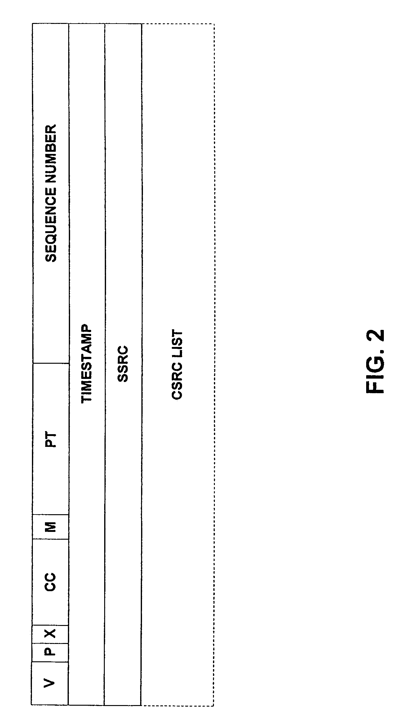
[0028]The identifier associated to a respective terminal might not be suited by itself to identify a transmitting terminal at a receiving terminal, like e.g. the randomly distributed SSRC identifier. In this case, preferably a mapping of the identifiers to a clear identification of the respective terminal is first transmitted from all possible transmitting terminals to the conference call server and further on to all possible receiving terminals. Then, each receiving terminal is able to map a later received identifier associated to a transmitting terminal to a corresponding identification of this terminal. The identification can be in particular a SIP address or a telephone number. The receiving terminal may also be able to further map the determined identification to another kind of identification. In case the identification is e.g. a SIP address or telephone number, the terminal may map this address or number to a name or an image stored in a directory of the receiving terminal.

Problems solved by technology

Obviously, in case none of the users participating in the conference call is talking for a while, none of the terminals will provide voice data for a while, and no terminal can be determined which provides voice data.

Method used


Image

  • Managing a packet switched conference call
  • Managing a packet switched conference call
  • Managing a packet switched conference call

Examples


Embodiment Construction

[0040]An embodiment of the method according to the invention will now be described with reference to FIGS. 1 to 3.

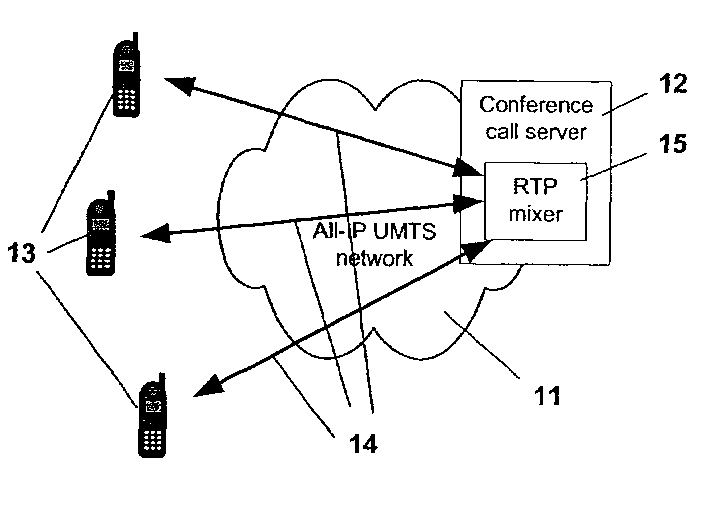
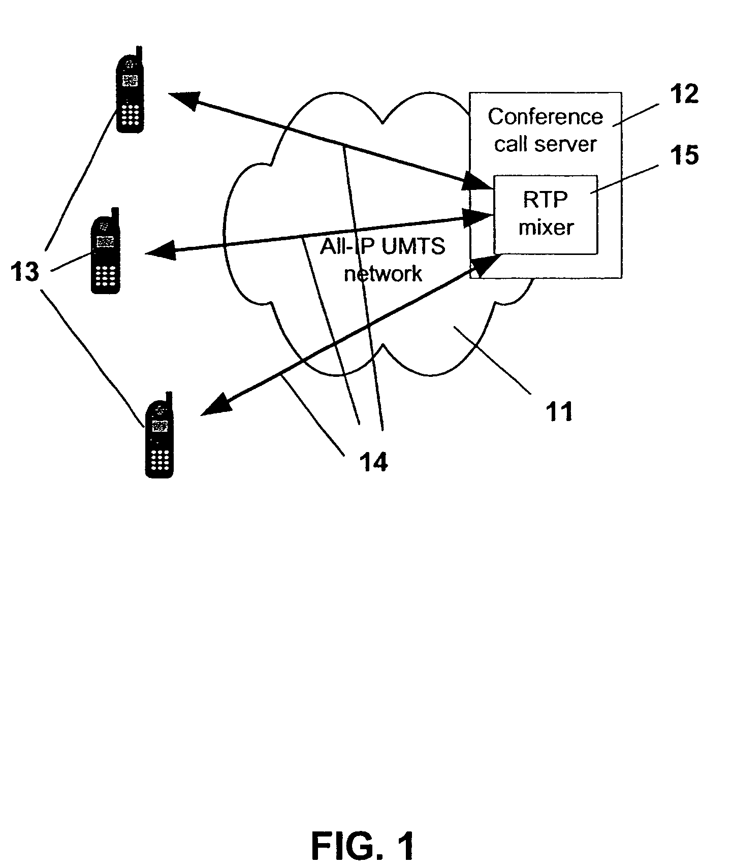
[0041]The embodiment supports the management of VoIP conference calls and is implemented in an RTP based system which comprises a UMTS network 11, a conference call server 12 including an RTP mixer 15 connected to the network 11 and a plurality of terminals 13. The terminals 13 can be connected to the conference call server 12 via the UMTS network 11 by means of RTP tunnels 14. The system thus corresponds in general to the system illustrated in FIG. 1, which has already been described above.

[0042]For setting up a VoIP conference call in this system, the Session Initiation Protocol (SIP) is used as signaling protocol. SIP is used together with the Session Description Protocol (SDP) to send invitations to the called parties and to agree on the voice codecs etc. The users of the terminals 13 join the conference either by initiating the session themselves by sending the SIP ...


PUM


Abstract

The invention relates to a method for managing a packet switched, centralized conference call between a plurality of terminals 13. In order to enable an enhancement of the user comfort, it is proposed that the method comprises at a conference call server 12 receiving data packets from all terminals 13. Based on these data packets, then at least one terminal 13 currently providing voice data is determined. In a next step, the data received in the data packets is mixed, and the mixed data is inserted into new data packets together with at least one identifier associated to one of the terminals 13 which were determined to provide voice data, such that the at least one identifier can be distinguished from any other information in the data packets. Finally, the new data packets are transmitted to terminals 13 participating in the conference call. The invention relates equally to a corresponding server and to a corresponding terminal.

Description

CROSS REFERENCE TO RELATED APPLICATION[0001]This application claims priority from International Application PCT / IB02 / 02625 filed Jul. 4, 2002.FIELD OF THE INVENTION[0002]The invention relates to a method for managing a packet switched centralized conference call between a plurality of terminals. The invention relates equally to a conference call server comprising means for managing a centralized conference call and to a terminal comprising means for participating in a centralized conference call.BACKGROUND OF THE INVENTION[0003]In a conference call, a group of terminal users is connected together in a way that when one of the participating users talks, all other participating users are able to hear the voice of the talking participant. In such a kind of communication, normally only one of the participating users is talking at a time, while the other users are listening. In a centralized conference call, the terminals of the participating users are not connected directly with each ot...

Claims


Application Information

Patent Timeline
Patent Type & Authority Patents(United States)
IPC IPC(8): H04M3/42H04L12/16H04M3/56H04L12/18H04L12/70H04L29/06H04M7/00
CPCH04L12/1822H04L29/06027H04M3/569H04M7/006H04L65/403H04L65/608H04L65/1006H04M2207/18H04L65/1104H04L65/65H04M3/56H04L12/18H04L2012/5603H04L65/1101
Inventor KUUSINEN, JARMOLAKANIEMI, ARI
Owner THINKLOGIX LLC
Learn More