
Detection of diastolic heart failure

a technology of diastolic heart failure and medical equipment, which is applied in the direction of electrotherapy, catheterization, blood vessel evaluation, etc., can solve the problems of difficult to separate diastolic and systolic heart failure, and achieve the effect of reducing peak and submaximal exercise performan

Inactive Publication Date: 2009-01-27
ST JUDE MEDICAL
View PDF5 Cites 1 Cited by
  • Summary
  • Abstract
  • Description
  • Claims
  • Application Information

AI Technical Summary

Benefits of technology

[0006]Thus with the present invention the reduced peak and submaximal exercise performance of DHF patients is utilized for detecting DHF. With the technique according to the invention it is possible to detect DHF at an early stage, often before the patient seem to have any symptoms.
[0008]In another embodiment of the apparatus according to the invention an averaging unit is provided to form an average value of pulse pressures during a plurality of cardiac cycles with the workload situation and an average value of pulse pressures measured during a number of cardiac cycles with the patient in rest. In this way the quality of the pulse pressure measurements is improved.
[0011]The invention also relates to a pacemaker provided with the apparatus for detecting DHF and a control that optimizes pacing therapy depending on the result of the comparison of the measured pulse pressures with the predetermined reference values. The pressure measuring unit of the apparatus according to the invention then preferably includes a pressure sensor connected to the pacemaker, since it can monitor the pulse pressure of its carrier for long periods. This is an advantage since evolvement of DHF is a slow process.

Problems solved by technology

In addition it has been hard to separate diastolic and systolic heart failure and they may also exist simultaneously.

Method used


Image

  • Detection of diastolic heart failure
  • Detection of diastolic heart failure
  • Detection of diastolic heart failure

Examples


Embodiment Construction

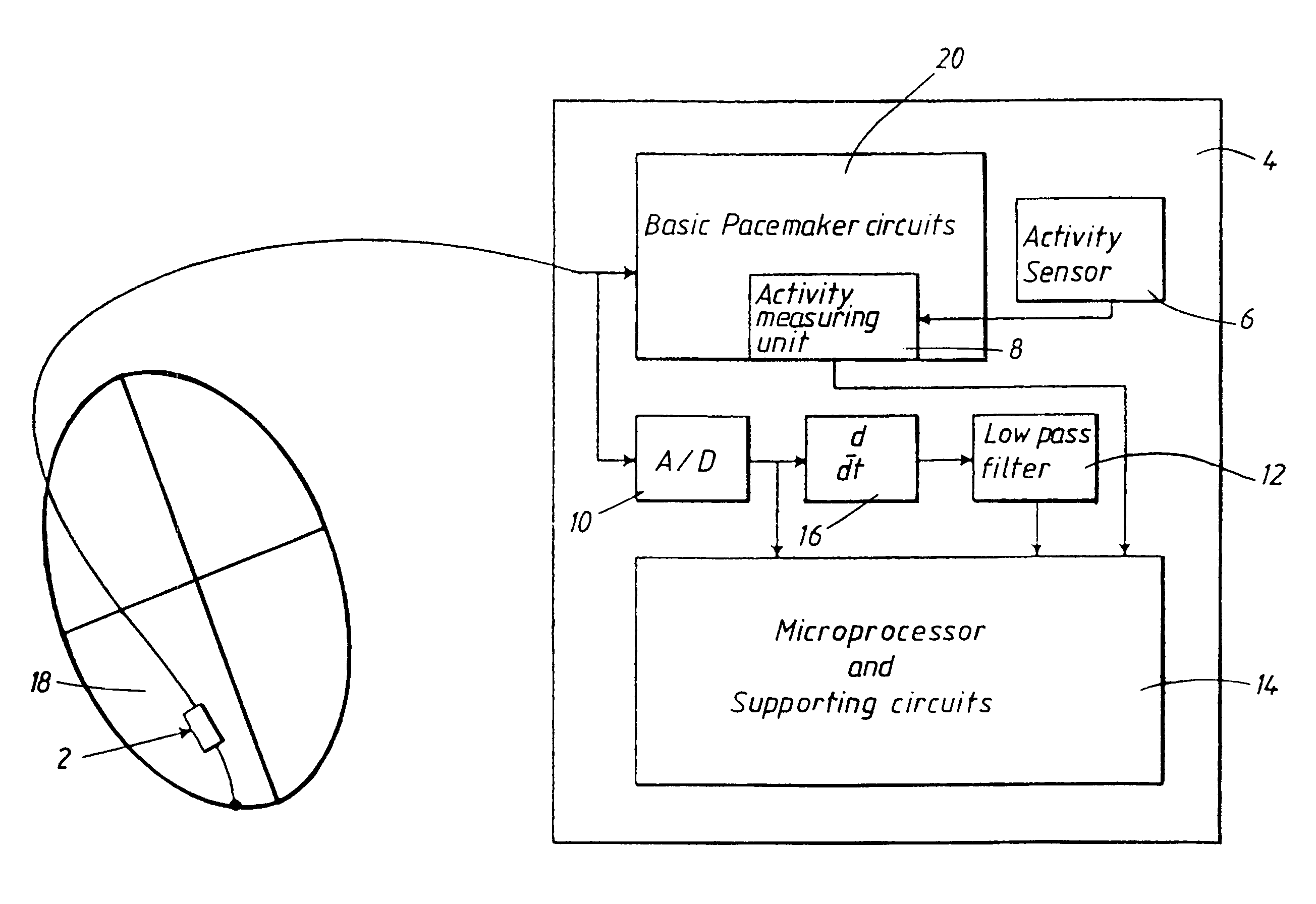
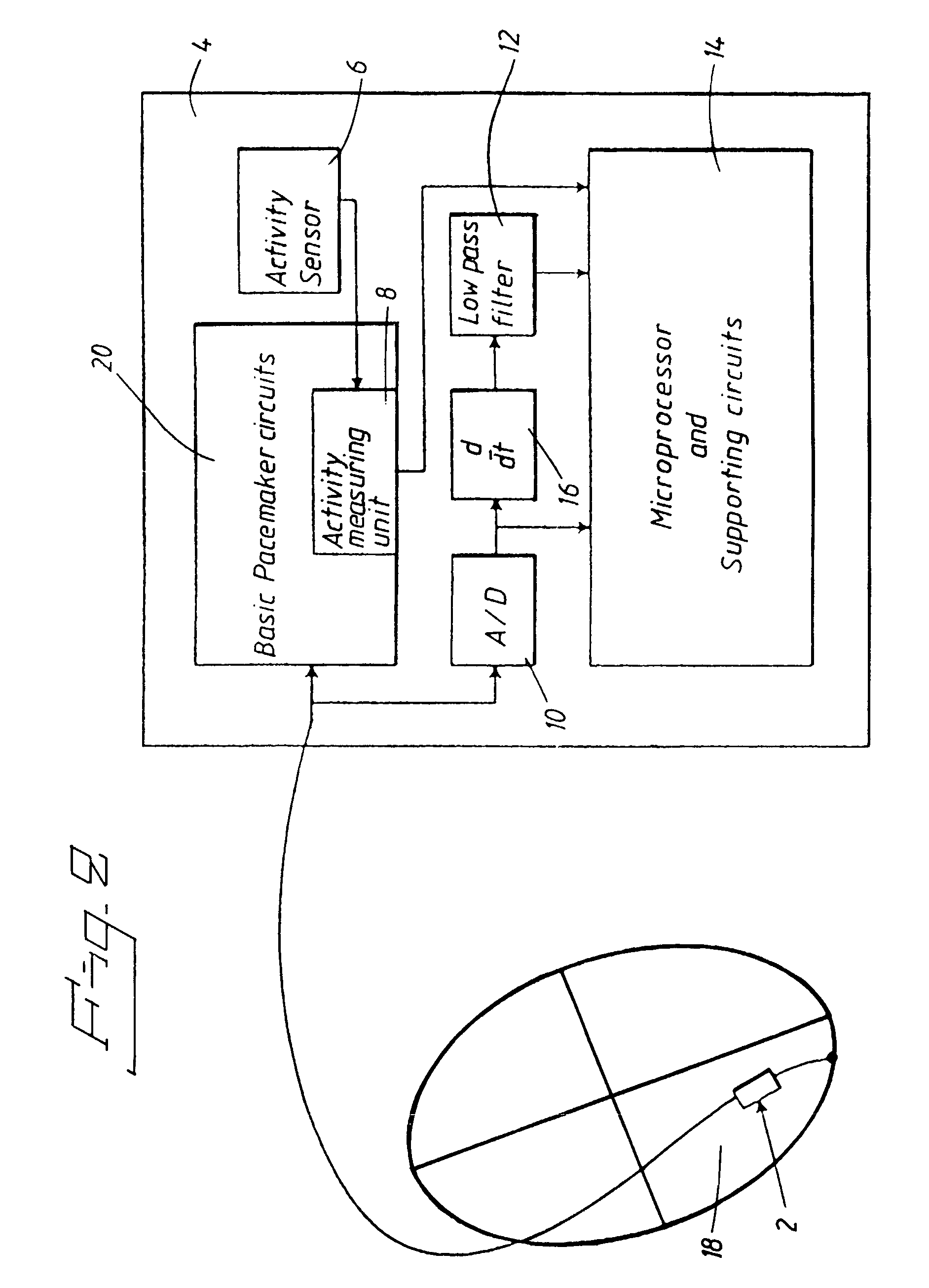
[0019]In the following an embodiment of the invention using a pressure sensor will be described, and the term pulse pressure means the varying pressure in aorta during a cardiac cycle.

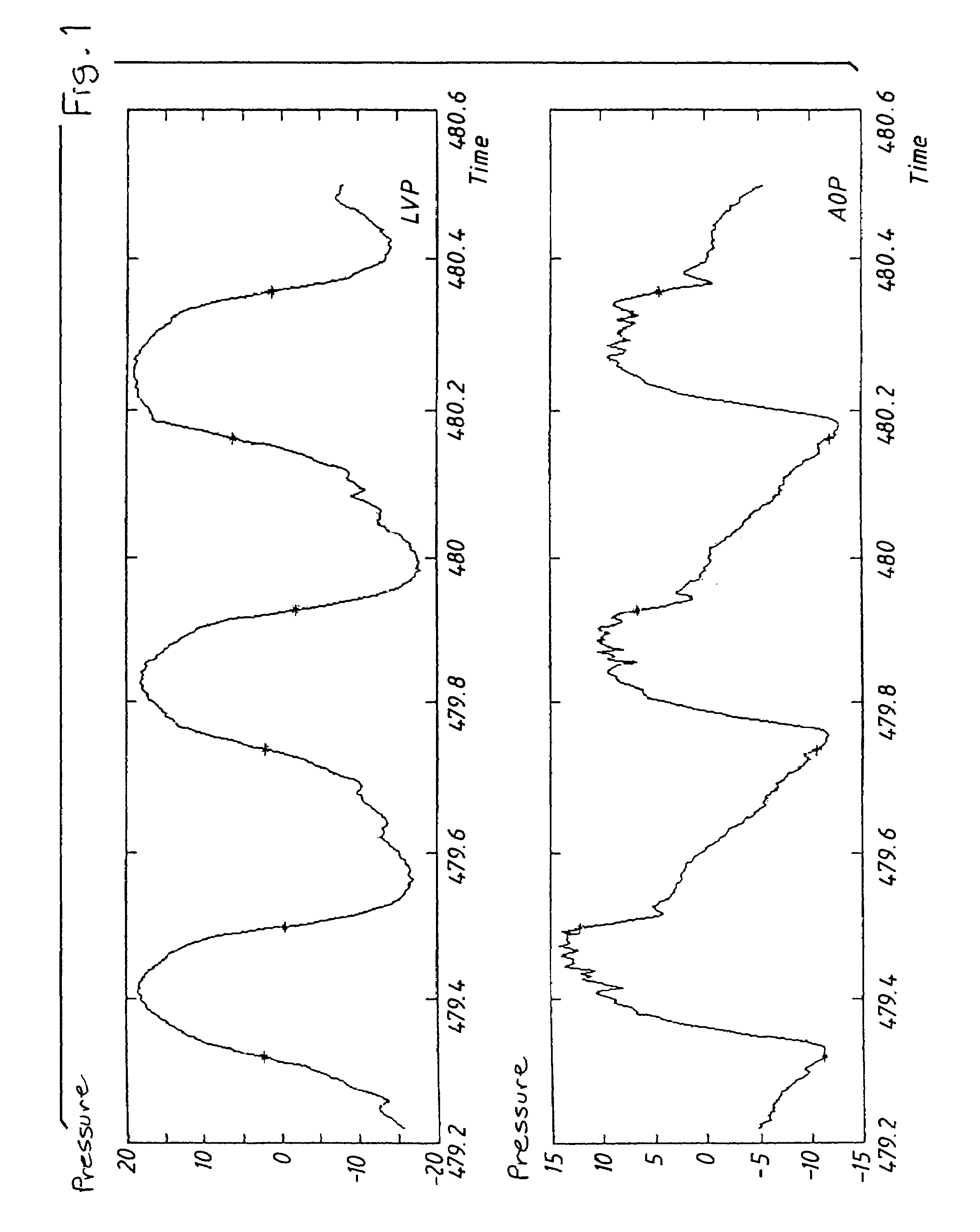
[0020]The above-mentioned pulse pressure can be obtained from the pressure measured in the left ventricle. In FIG. 1 the top curve shows the left ventricular pressure and the curve below the aortic pressure as a function of time. The magnitude of the pressures are indicated in arbitrary units in FIG. 1.

[0021]The asterisks in the curves of FIG. 1 denote time points for the maxima and minima of the time derivative of the left ventricular pressure, dLVP / dtmax and dLVP / dtmin respectively. As the aortic valves open close to the point dLVP / dtmax, the aortic pressure is close to the left ventricular pressure at this point of time.

[0022]During the period from dlVP / dtmax to dLVP / dtmin blood flows into aorta. The maximum of aortic pressure is situated in this period. The pulse pressure consequently can be obtain...


PUM


Abstract

An implantable medical apparatus for detecting diastolic heart failure, DHF, has a DHF determining device for determining at least one blood pressure parameter for detecting a DHF state of the heart of a patient. The DHF determining device includes a pressure measuring unit for measuring pulse pressure in a cardiac cycle for a predetermined workload situation of the patient as the blood pressure parameter, and a comparator compares the measured pulse pressure with a predetermined reference value. A pacemaker includes such an apparatus and a control unit that optimizes pacing therapy depending on the result of the comparison of the measured pulse pressures with the predetermined reference values. A corresponding method of detecting diastolic heart failure, DHF, includes the step of determining at least one blood pressure parameter for detecting a DHF state of the heart of a patient by determining, as said blood pressure parameter, the pulse pressure in a cardiac cycle for a predetermined workload situation of the patient, and the determined pulse pressure is compared with a predetermined reference value.

Description

BACKGROUND OF THE INVENTION[0001]1. Field of the Invention[0002]The present invention relates to an implantable medical apparatus for detecting diastolic heart failure (DHF), of the type having a DHF determining device for determining at least one blood pressure parameter for detecting a DHF state of the heart of a patient. The invention also relates to a pacemaker provided with such an apparatus, and a method of detecting DHF, including the step of determining at least one blood pressure parameter for detecting a DHF state of the heart of a patient.[0003]2. Description of the Prior Art[0004]There is a growing recognition that congestive heart failure caused by a predominant abnormality in the diastolic function, i.e. diastolic heart failure, DHF, is both common and causes significant morbidity and mortality. Therefore early detection of DHF is important. Patients do not, however, seem to have symptoms at an early stage. In addition it has been hard to separate diastolic and systoli...

Claims


Application Information

Patent Timeline
Patent Type & Authority Patents(United States)
IPC IPC(8): A61N1/00A61B5/021A61B5/0215A61N1/362A61N1/365A61N1/37
CPCA61B5/021A61N1/3627A61N1/3702A61B5/02154A61N1/36564
Inventor HEDBERG, SVEN-ERIKBJORLING, ANDERSTORPO, MARIALJUNGSTROM, KARIN
Owner ST JUDE MEDICAL
Learn More