Method for the creation of a hybrid cycle simulation model

a hybrid cycle and simulation model technology, applied in the field of cycle simulation, can solve the problems of small event traces for problem debugging, the inability to effectively validate functions like clocking, phased lock loops and built-in self-tests, and the inability to effectively validate functions in a 1-cycle simulation environment. achieve the effect of improving performan

Inactive Publication Date: 2009-01-27
GLOBALFOUNDRIES INC
View PDF7 Cites 22 Cited by
  • Summary
  • Abstract
  • Description
  • Claims
  • Application Information

AI Technical Summary

Benefits of technology

[0018]In general, 1-cycle representations can provide speed and size advantages over a more logically accurate 2-cycle representation for components where there is no logic between the L1 and L2 latches, and the L1 latch output is not used to feed other logic. This is due to the fact that an L2-only latch consumes half the space (or less) of that needed to represent an L1-L2 latch in a cycle simulator. Some logic components cannot be abstracted to representation by L2-only latches, but it may be desirable to verify the operation of these components in concert with the vast majority of logic which can be abstracted. Rather than expend the performance and size penalty for using a model of solely non-abstracted components, it is possible to construct a hybrid model which is a mix of the non-abstracted components and abstracted components. Further, it may be beneficial to entirely omit logic for some components where they are not required for the verification of some subset of function, or are slated be replaced with an alternate behavior. This behavior is often provided by an external source working through an API into the cycle simulator or written in a hardware design language.

Problems solved by technology

This increased complexity translates to substantial development and manufacturing expense, which is directly proportional to the number of design fabrication iterations.
For example, functions like clocking, phased lock loops and Built-In Self Test (BIST) can rarely be effectively validated in a 1-cycle simulation environment.
Smaller model size is particularly important on hardware simulators with limited capacity and resulting in smaller event traces for problem debug.
The disadvantage is that behavioral “black boxes” are required to represent some parts of the design, such as the aforementioned functions.
While significantly faster than an event simulation, the 2-cycle simulation has slower performance than a 1-cycle simulation and is larger in size.
While the aforementioned inventions are considered innovative in the area of hardware design verification, none of them, either individually, or taken in combination, address the need to balance simulation performance throughput against behavioral accuracy in a cycle simulation environment.

Method used


Image

  • Method for the creation of a hybrid cycle simulation model
  • Method for the creation of a hybrid cycle simulation model
  • Method for the creation of a hybrid cycle simulation model

Examples


Embodiment Construction

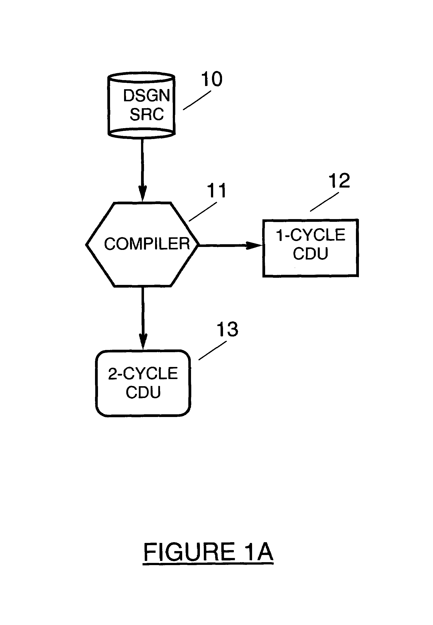
[0043]Turning now to the drawings in greater detail, it will be seen that FIG. 1A depicts a flowchart comprising the steps for building a plurality of compiled data units (hereafter referred to as CDUs) which represent the critical component of a hybrid cycle simulation model build process. The preferred embodiment enables the cycle simulation models to be constructed using 1-cycle (also known as single cycle) CDUs, 2-cycle CDUs or a combination thereof.

[0044]As seen in FIG. 1A, the Design Source (10) is fed into a Compiler (11). In our preferred embodiment, the Design Source is represented by the VHDL hardware description language wherein said Design Source (10) is described at the register transfer level (RTL). One skilled in the art can appreciate that the present invention is applicable to alternate design source descriptions, such as, but not limited to, Verilog, JHDL and the like. The Compiler (11) step in FIG. 1A represents any hardware description language compiler used to d...


PUM


Abstract

Disclosed is a method for constructing a Hybrid Cycle Simulation model comprising Compiled Data Units (CDUs) for use in design verification. The simulation model may contain a plurality of 1-cycle CDUs, optimized for simulation throughput, and 2-cycle CDUs, optimized for simulation accuracy, or a mixture thereof. Utilizing a netlist tool extracting hierarchical design source components for use, the construction checks that all inputs and outputs of any hierarchical design source components bind, and employs Object Traversal Directives for incorporating the selected CDUs into the simulation model. A data management method is used for tracking the validity of the components in the model. Additionally, a software entity (FACDDR) permits high bandwidth simulation of design components normally requiring cycle accurate simulation. FACDDR provides linkages for standard logic elements for abstracting one or more design interface components out of a cycle simulation environment and design interface emulation of an interface which interacts with a cycle simulation model through an API to extract present value of driving side signals of an interface and to set the cycle simulation model on the receiving side.

Description

TRADEMARKS[0001]IBM® is a registered trademark of International Business Machines Corporation, Armonk, N.Y., U.S.A. Other names used herein may be registered trademarks, trademarks or product names of International Business Machines Corporation or other companies.SECTION 1.01 BACKGROUND OF THE INVENTION[0002]1. Field of the Invention[0003]This invention relates to the field of computer hardware design verification, specifically in the area of cycle simulation. Disclosed herein is a method for constructing a Hybrid Cycle Simulation model comprised of a mixture of Compiled Data Units (CDUs). Said simulation model may contain a plurality of 1-cycle CDUs, optimized for simulation throughput, and 2-cycle CDUs, optimized for simulation accuracy. Additionally, the present invention contemplates a software entity FACDDR which implements a method to permit high bandwidth simulation of design components normally requiring cycle accurate simulation.[0004]2. Description of Background[0005]There...

Claims


Application Information

Patent Timeline
Patent Type & Authority Patents(United States)
IPC IPC(8): G06F17/50G06F9/44
CPCG06F17/5022G06F30/33
Inventor VAN HUBEN, GARY A.KAMINSKI, JR., EDWARD J.HUSTON, ELSPETH ANNE
Owner GLOBALFOUNDRIES INC
Why Eureka
Try Eureka