
Remote radius inspection tool for composite joints

a composite joint and inspection tool technology, applied in the direction of instruments, heat measurement, specific gravity measurement, etc., can solve the problems of difficult to fully inspect the limited access of the feature requiring inspection, the inability of manual inspection by a technician, and the inability to fully inspect the limited access of the structure, etc., to achieve convenient and reliable inspection of features

Inactive Publication Date: 2009-02-03
THE BOEING CO
View PDF44 Cites 26 Cited by
  • Summary
  • Abstract
  • Description
  • Claims
  • Application Information

AI Technical Summary

Benefits of technology

The present invention provides a non-destructive inspection device for inspecting features of a structure, such as limited-access features. The device includes an actuating portion and an inspecting portion that moves in concert with the actuating portion. The inspecting portion includes a housing, an inspection sensor, and at least one magnet. The actuating portion also includes at least one magnet so that when the actuating portion is placed on a surface of the structure and the inspecting portion is positioned on the opposite surface, the two portions are magnetically coupled so that movement of the actuating portion causes the inspecting portion to move in concert with the actuating portion without the inspecting portion directly contacting the actuating portion. The inspection sensor is selectively moveable relative to the housing of the inspecting portion. The device and method provide for convenient and reliable inspection of features of a structure.

Problems solved by technology

Access to the feature requiring inspection may be so limited that a manual inspection by a technician is not possible.
Limited-access features of a structure, such as the close-out joints, are difficult to fully inspect using contemporary inspection devices.

Method used


Image

  • Remote radius inspection tool for composite joints
  • Remote radius inspection tool for composite joints
  • Remote radius inspection tool for composite joints

Examples


Embodiment Construction

[0025]At least six embodiments of the present invention will be described more fully with reference to the accompanying drawings. The invention may be embodied in many different forms and should not be construed as limited to only the embodiments described and shown. Like numbers refer to like elements throughout.

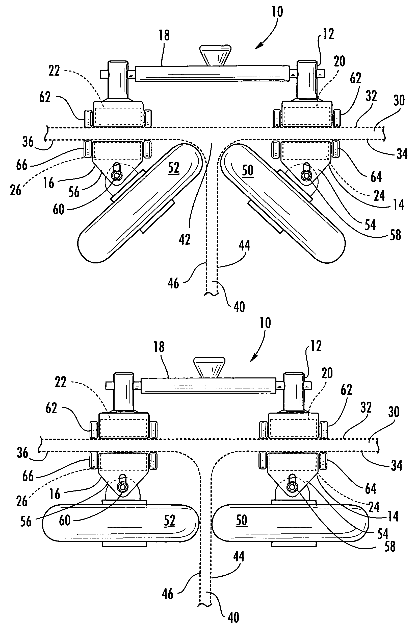
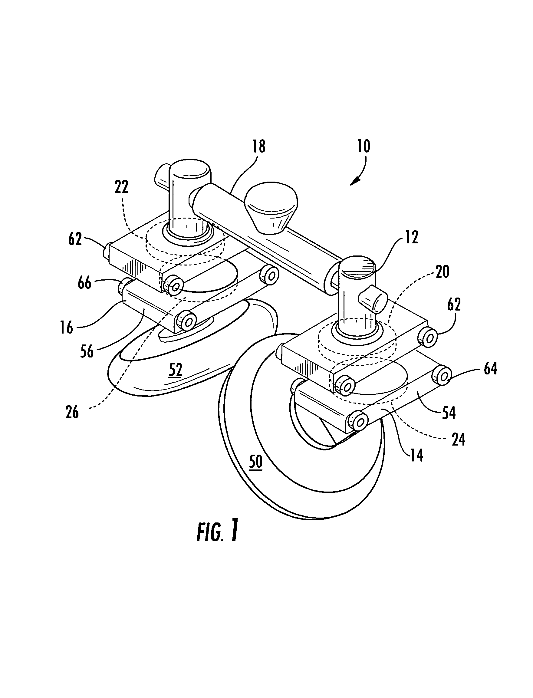
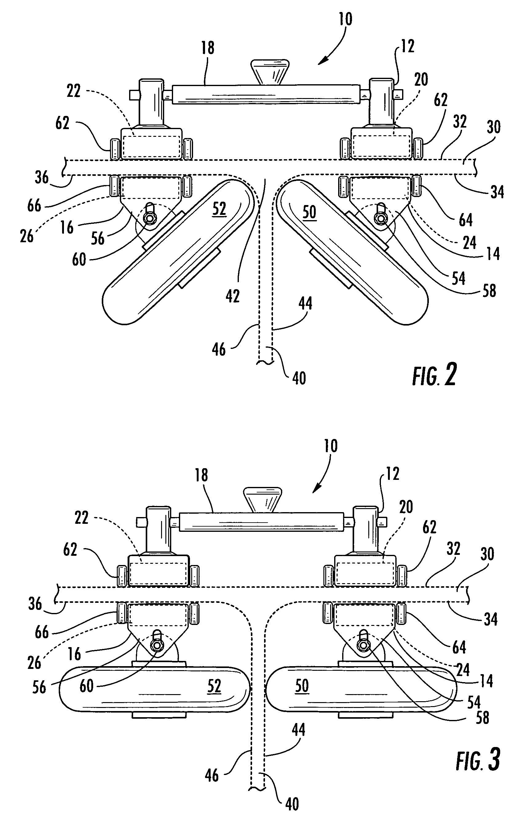
[0026]With reference to FIGS. 1-13, non-destructive inspection devices in accordance with various embodiment of the present invention are illustrated. Referring to the embodiment of FIGS. 1-3, the non-destructive inspection device 10 includes an actuating portion 12, a first inspecting portion 14, and a second inspecting portion 16. The actuating portion 12 and the inspecting portions 14 and 16 are individual portions and are not directly connected in the illustrated embodiment. The actuating portion 12 is structured for placement on a surface of the structure undergoing inspection. The inspecting portions 14 and 16 are structured for positioning on a surface opposite the s...


PUM

PropertyMeasurementUnit
structureaaaaaaaaaa
structuresaaaaaaaaaa
flexibilityaaaaaaaaaa

Abstract

There is provided a non-destructive inspection device having an actuating portion and at least one inspecting portion. The inspecting portion(s) are magnetically coupled to the actuating portion so that the inspecting portion(s) may be moved into limited-access areas to inspect features of a structure. The inspecting portion(s) each include at least one inspection sensor that transmits and / or receives signals that, when processed, indicate defects in the features of the structure. The inspection sensor of the inspecting portion is moveable relative to the housing of the inspecting portion to enable inspection of relatively larger areas of the structure being inspected. The inspection sensors may be moved, relative to the housing of the inspecting portion, manually and / or automatically.

Description

CROSS-REFERENCES TO RELATED APPLICATIONS[0001]This application is a continuation-in-part of U.S. patent application Ser. No. 10 / 734,452, filed on Dec. 12, 2003, now U.S. Pat. No. 6,993,971 and U.S. patent application Ser. No. 10 / 752,890, filed on Jan. 07, 2004, now U.S. Pat. No. 7,321,971 which are hereby incorporated herein in their entirety by reference.FIELD OF THE INVENTION[0002]The present invention relates generally to non-destructive inspection devices. More particularly the invention relates to an inspection device for inspecting limited-access features of a structure.BACKGROUND OF THE INVENTION[0003]Non-destructive inspection of structures involves thoroughly examining a structure without harming the structure or requiring significant disassembly of the structure. Non-destructive inspection is advantageous for many applications in which a thorough inspection of the exterior and / or interior of a structure is required. For example, non-destructive inspection is commonly utili...

Claims


Application Information

Patent Timeline
Patent Type & Authority Patents(United States)
IPC IPC(8): G01N29/265
CPCG01N29/07G01N29/225G01N29/2493G01N29/265G01N2291/02854G01N2291/0422G01N2291/101G01N2291/102G01N2291/2694
Inventor GEORGESON, GARY E.FOGARTY, MICHAEL D.
Owner THE BOEING CO
Learn More