Combustion-engined setting tool

a technology of combustion engine and setting tool, which is applied in the direction of nailing tools, manufacturing tools, machines/engines, etc., can solve the problems of malfunctioning setting tools, little time available for feeding new nails in the nail guide, etc., and achieves the effect of reducing losses, simple structure, and easy sealing of displacement bodies

Active Publication Date: 2009-02-03
HILTI AG
View PDF4 Cites 10 Cited by
  • Summary
  • Abstract
  • Description
  • Claims
  • Application Information

AI Technical Summary

Benefits of technology

[0012]According to an advantageous embodiment of the present invention the compression device includes a charging cylinder to which fuel and oxidant are delivered, and a displacement body, displaceable in the charging cylinder and connectable with the ventilator drive. The charging cylinder is constructively very simple and provides for an easy sealing of the displacement body.
[0013]Advantageously, the take-off drive of the ventilator drive is connected with a gear drive that is connected with operational elements for the displacement body by an appropriate coupling. The foregoing measure insures that the drive energy necessary for the compression device is taken off the ventilator drive only for a short time, which reduces losses to a minimum. The drive connection between the ventilator drive and the compression device can be turned on and off by the coupling, so that the drive energy for the compression device is taken off only when necessary.
[0018]Advantageously, the valve means includes an actuator cooperating with at least one driver element of a component displaceable relative to the charging cylinder for displacing the valve means from the first position to the second position upon the setting tool being pressed against a constructional component, and from the second position to the first position upon lifting of the setting tool off the constructional component. The displaceable component can be formed, e.g., by a guide sleeve in which the piston guide is located, or another element of the press-on string. Thereby, the valve means is automatically controlled in a technically simple manner by the setting tool being pressed against or being lifted off the constructional component.

Problems solved by technology

The drawback of the setting tool of the U.S. Pat. No. 4,403,722 consists in that the combustion in the combustion chamber occurs under the atmospheric pressure, so that peak pressures achieved during combustion usually lie within a range between 5-6 bar.
The drawback of the setting tool of U.S. Pat. No. 4,415,110 consists in that the stem of the setting piston, in its initial position at the end region of the second cylinder remote from the spark plug, is located in the nail guide, blocking feeding of a new nail.
Therefore, little time is available for feeding a new nail in the nail guide when the setting piston is located in the region of the second cylinder adjacent to the spark plug therein.
This is critical when longer nails are being driven in, and it can lead to malfunction of the setting tool.

Method used


Image

  • Combustion-engined setting tool
  • Combustion-engined setting tool
  • Combustion-engined setting tool

Examples


Embodiment Construction

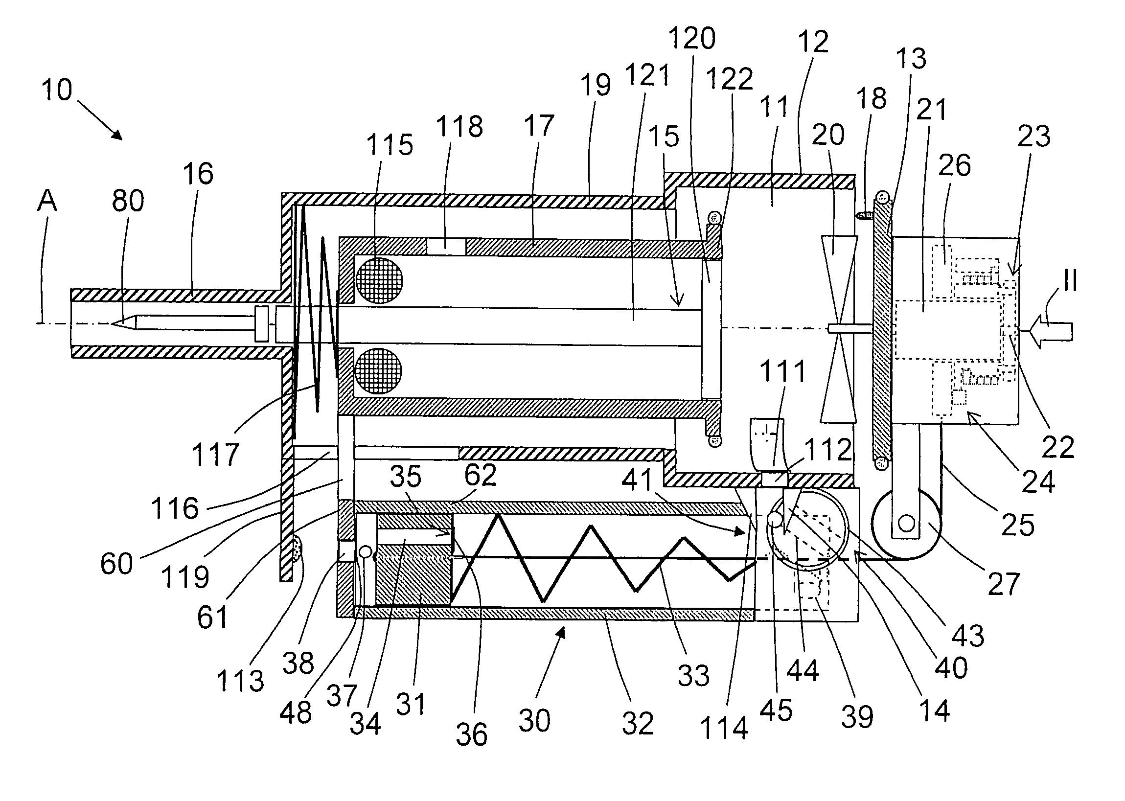
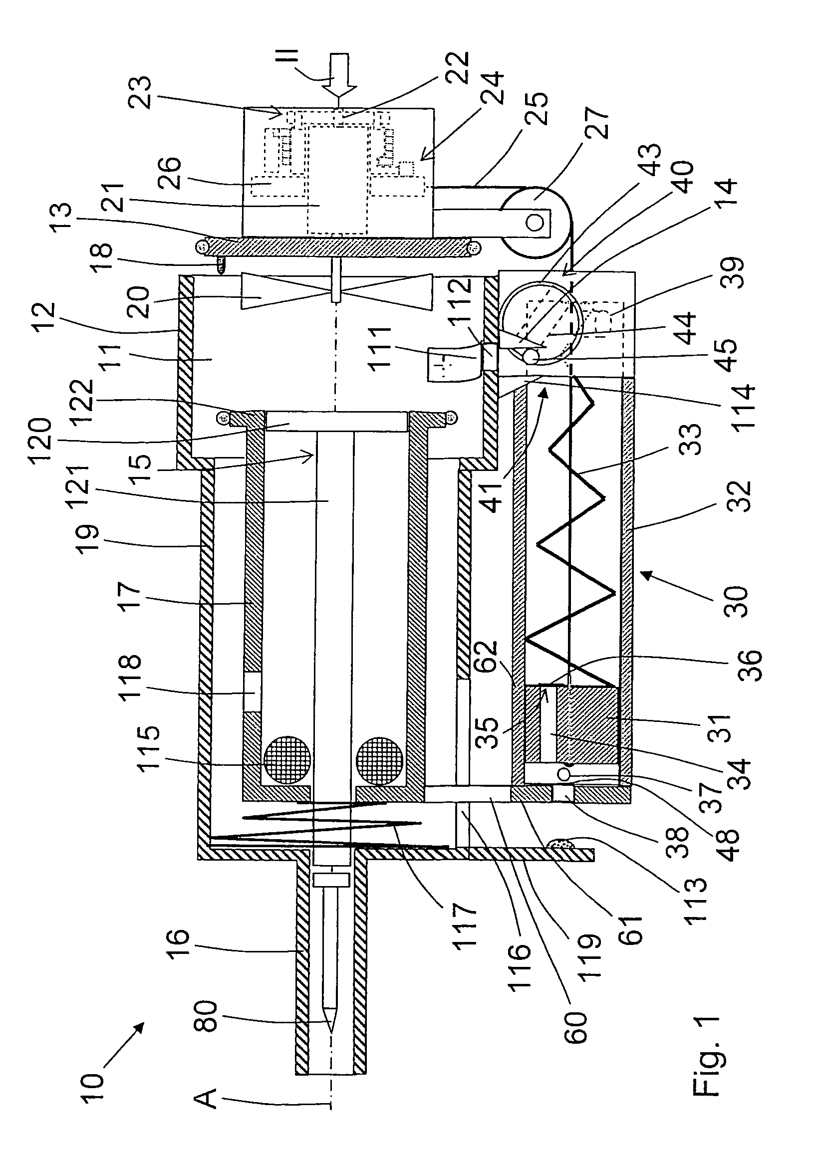
[0025]A setting tool 10 according to the present invention, which is shown in FIGS. 1-4, can operate with a fuel gas or an evaporated liquid fuel. The setting tool 10 includes a setting mechanism with which a fastening element 80 such as nail, bolt, etc. is driven in a constructional component U when the setting tool 10 is pressed against the constructional component with its bolt guide 16 or its nose part.

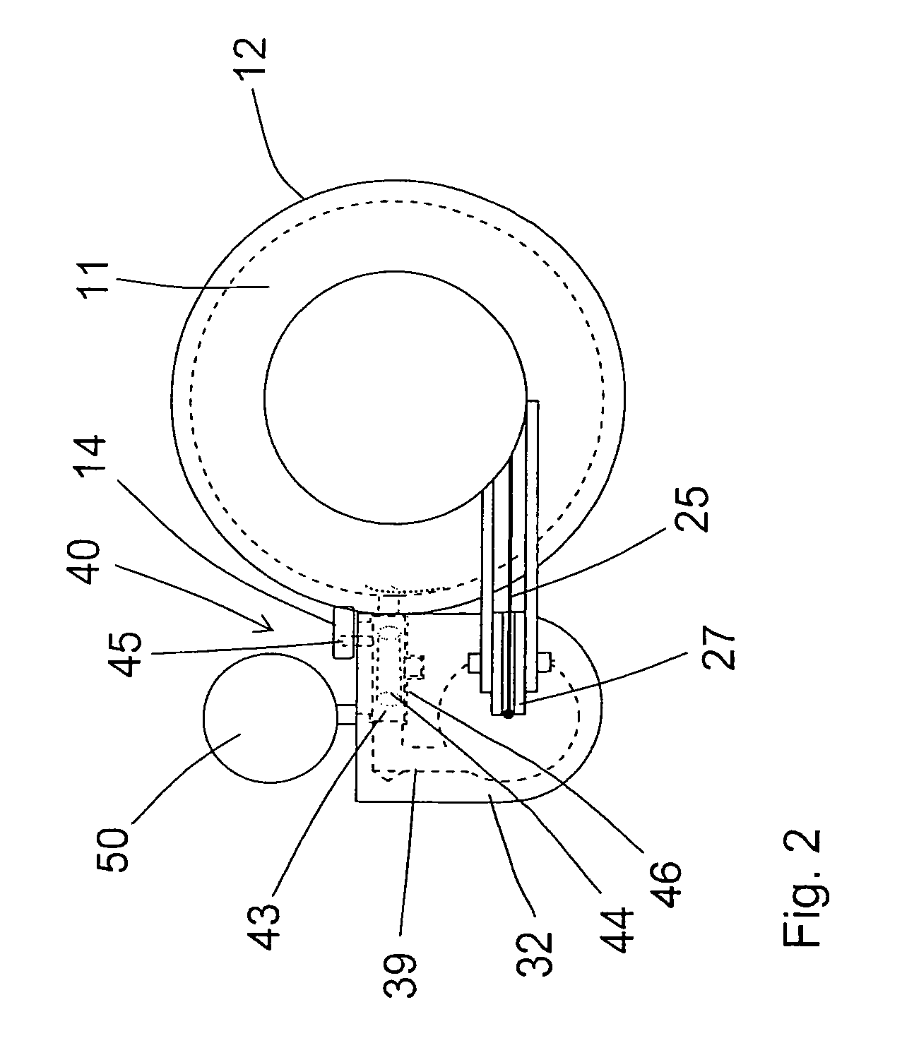
[0026]The setting mechanism includes, among others, a combustion chamber 11 formed in a combustion chamber sleeve 12 and which is closed by closing means 13 formed as a rear wall plate, a piston guide 17 in which a drive piston 15 is displaceably arranged, and a bolt guide 16 for guiding the fastening element 80. The drive piston 15 has a stem 121 that drives the fastening element 80. The piston guide 17 is formed as an elongate cylinder that defines a longitudinal axis A of the setting tool 10. The piston guide 17 and the closing means 13 are connected with each other and form a ...


PUM


Abstract

A combustion-engined setting tool for driving fastening elements in a constructional component includes at least one combustion chamber (11) for receiving an oxidant-fuel gas mixture, a piston guide (17) located adjacent to the combustion chamber (11), and in which a drive piston (15) for driving the fastening elements in is displaceable by combustion gases, a ventilator for creating turbulence in the combustion chamber (11), and a compression device (30) for compressing gases fed into the combustion chamber (11) and driven by the ventilator drive (21).

Description

BACKGROUND OF THE INVENTION[0001]1. Field of the Invention[0002]The present invention relates to a combustion-engined setting tool for driving fastening elements such as nails, bolts, pins and the like in a constructional component and including at least one combustion chamber for receiving an oxidant-fuel gas mixture, a piston guide located adjacent to the combustion chamber and in which a drive piston for driving the fastening elements in is displaceable by combustion gases produced by combustion of the oxidant-fuel gas mixture in the combustion chamber, and ventilator means for producing turbulence in the combustion chamber and including a ventilator drive.[0003]2. Description of the Prior Art[0004]Setting tools of the type described above can be driven with gaseous or evaporated liquid fuels that are combusted in the combustion chamber, driving a setting or drive piston for the fastening elements. Generally, with such setting tools, it is desirable to achieve the most possible t...

Claims


Application Information

Patent Timeline
Patent Type & Authority Patents(United States)
IPC IPC(8): B25C1/08
CPCB25C1/08
Inventor GSCHWEND, HANSSCHIESTL, ULRICHHANNOSCHOECK, NIKOLAUS
Owner HILTI AG
Why Eureka
Try Eureka