
Switch machine for railway and tramway switches or the like

a technology for tramways and switches, applied in the direction of transportation and packaging, point-of-use vehicles, roads, etc., can solve the problem that the railability of switches requires higher construction costs, and achieve the effect of limiting both fabrication and storage costs, and fast and more effective fabrication

Active Publication Date: 2009-02-03
ALSTOM FERROVIARIA SPA
View PDF2 Cites 11 Cited by
  • Summary
  • Abstract
  • Description
  • Claims
  • Application Information

AI Technical Summary

Benefits of technology

[0009]The present invention has the object of providing a switch machine as described hereinbefore, allowing by inexpensive arrangements a faster and more effective fabrication and limiting both fabrication and storage costs.
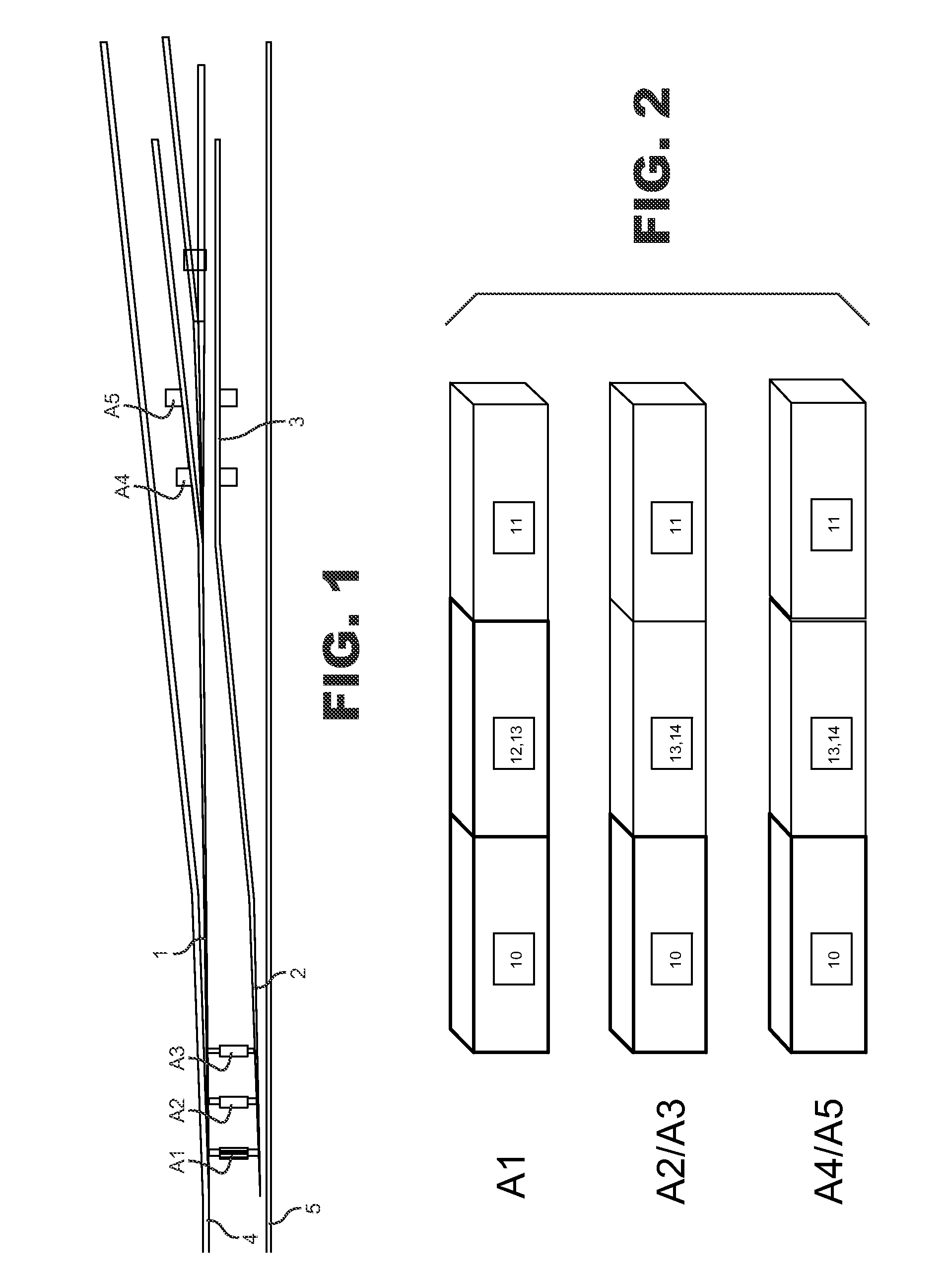
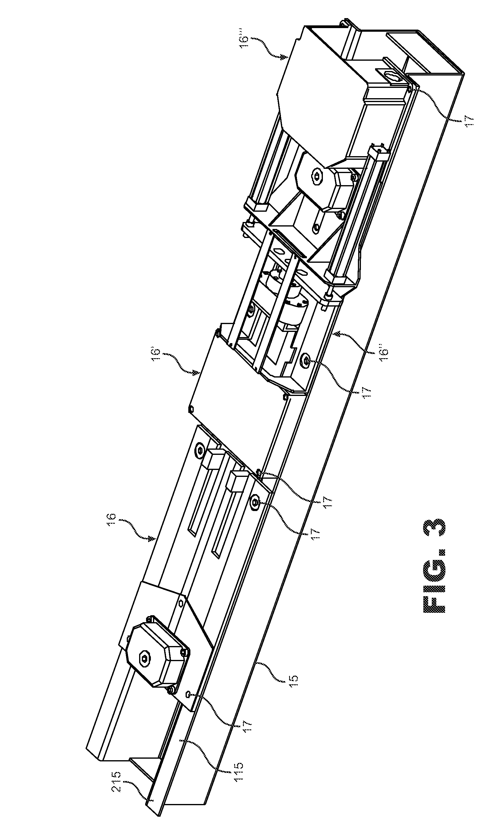
[0017]The advantages of the present invention are self-evident from the above description. In fact, the different switch machine types only differ from each other in a few operating units, particularly in the transmission and point locking modules. The switch machines for the point heels and the frog have the same motor modules, the same casing and the same transmission module. The only difference lies in the different coupling and point locking modules of switch machines for the point heels and for the intermediate portions and the frog. This obviously provides a higher production effectiveness and cost reduction, for fabrication and storage or purchasing by the contractors that manufacture said operating units. Obvious advantages are also obtained in terms of maintenance and availability of spare parts. Also, as regards construction, the switch machines of this invention are easy and fast to assemble, as modularity requires simple means for unique predetermined fastening of the operating units to each other and to the housing.

Problems solved by technology

Obviously, the trailability of a switch machine requires higher construction costs; moreover, in switches with very long switch points, trailability is only required for the switch machine / s at the heels of the switch points, whereas in the intermediate portion and at the frog, given a typical train passage situation, as described above, the train wheels do not exert any thrust forces on the switch points.

Method used


Image

  • Switch machine for railway and tramway switches or the like
  • Switch machine for railway and tramway switches or the like
  • Switch machine for railway and tramway switches or the like

Examples


Embodiment Construction

[0030]FIG. 1 is a schematic view of a railway line segment, which includes a switch.

[0031]The switch has a pair of switch points 1, 2, starting at a so-called frog 3 and terminating by their free ends in an intermediate position between the rails 4, 5 of a track.

[0032]In order to cause the train to divert its route from the straight track over a branch line, the switch points 1, 2 are alternately movable to a so-called thrown position, abutting against the corresponding rail. This motion is controlled by so-called switch machines. The switch as shown in FIG. 1 has long switch points, as is preferably used in high speed lines. To this end, in order to ensure a better motion of the two switch points between the two opposed thrown positions, multiple switch machines are provided, the main switch machine, denoted A1, being at the free heel of the points, one or more intermediate switch machines A2, A3, being arranged along the points 1, 2, between the main switch machine A1 and the frog...


PUM


Abstract

A switch machine for railway and tramway switches or the like, having an enclosure for its operating units of the same size as a tie and adapted to be used like a tie, characterized in that the switch machine has a modular construction.

Description

FIELD OF THE INVENTION[0001]The present invention relates to a switch machine for railway and tramway switches or the like, having an enclosure for its operating units of the same size as a tie and adapted to be used like a tie.BACKGROUND OF THE INVENTION[0002]Switch machines for railway and tramway switches are well known and have considerable advantages.[0003]Particularly in high speed railway lines, switches have relatively long switch points to provide such a wide radius of curvature as to withstand the high speed of the train. Unlike conventional switches, in which a switch machine is provided at the heels of the switch points and an additional switch machine is possibly provided at the frog of the switch points, high speed switches as described hereinbefore have multiple switch machines arranged all along the switch points, to keep the latter in the proper curvature condition as the train passes thereon.[0004]Switch machines have the function of displacing switch points betwee...

Claims


Application Information

Patent Timeline
Patent Type & Authority Patents(United States)
IPC IPC(8): E01B7/00B61L5/00B61L5/06B61L5/10
CPCB61L5/065B61L5/10B61L5/06
Inventor CAVALLI, SILVANO
Owner ALSTOM FERROVIARIA SPA
Learn More