Head rests

a head rest and seat technology, applied in the direction of head rests, vehicle components, vehicle arrangements, etc., can solve the problems of inability to accurately detect the head position of passengers, the main body of the head rest cannot be moved or actuated, and the main body of the head rest cannot be appropriately positioned relative to the passenger head

Inactive Publication Date: 2009-02-03
TOYOTA BOSHOKU KK +1
View PDF14 Cites 21 Cited by
  • Summary
  • Abstract
  • Description
  • Claims
  • Application Information

AI Technical Summary

Benefits of technology

[0007]It is, accordingly, one object of the present invention to provide improved head rests for a vehicle, in particular, to provide head rests in which a head rest main body can always be appropriately positioned relative to a head of a passenger when the passenger is sitting on a vehicle seat.
[0009]According to this embodiment, the moving mechanism may be controlled after the sensitivity of the head detecting device reaches a predetermined value. Therefore, the moving mechanism can be accurately controlled based on the control signal from the head detecting device. As a result, the head support portion can be reliably positioned at the optimal proximity position relative to the passenger head. Thus, the passenger head can be suitably held by the head support portion when a vehicle collides.

Problems solved by technology

However, such sensors cannot accurately detect the passenger head position if the sensors are positioned away from the passenger head over a desired distance.
Therefore, if the head rest main body is positioned excessively away from the passenger head when the passenger is sitting on a vehicle seat, the head rest main body cannot be moved or actuated.
Consequently, in such a case, the head rest main body cannot be appropriately positioned relative to the passenger head.

Method used


Image

  • Head rests
  • Head rests
  • Head rests

Examples


Embodiment Construction

[0026]A representative example of the present invention has been described in detail with reference to the attached drawings. This detailed description is merely intended to teach a person of skill in the art further details for practicing preferred aspects of the present teachings and is not intended to limit the scope of the invention. Only the claims define the scope of the claimed invention. Therefore, combinations of features and steps disclosed in the foregoing detailed description may not be necessary to practice the invention in the broadest sense, and are instead taught merely to particularly describe detailed representative examples of the invention. Moreover, the various features taught in this specification may be combined in ways that are not specifically enumerated in order to obtain additional useful embodiments of the present teachings.

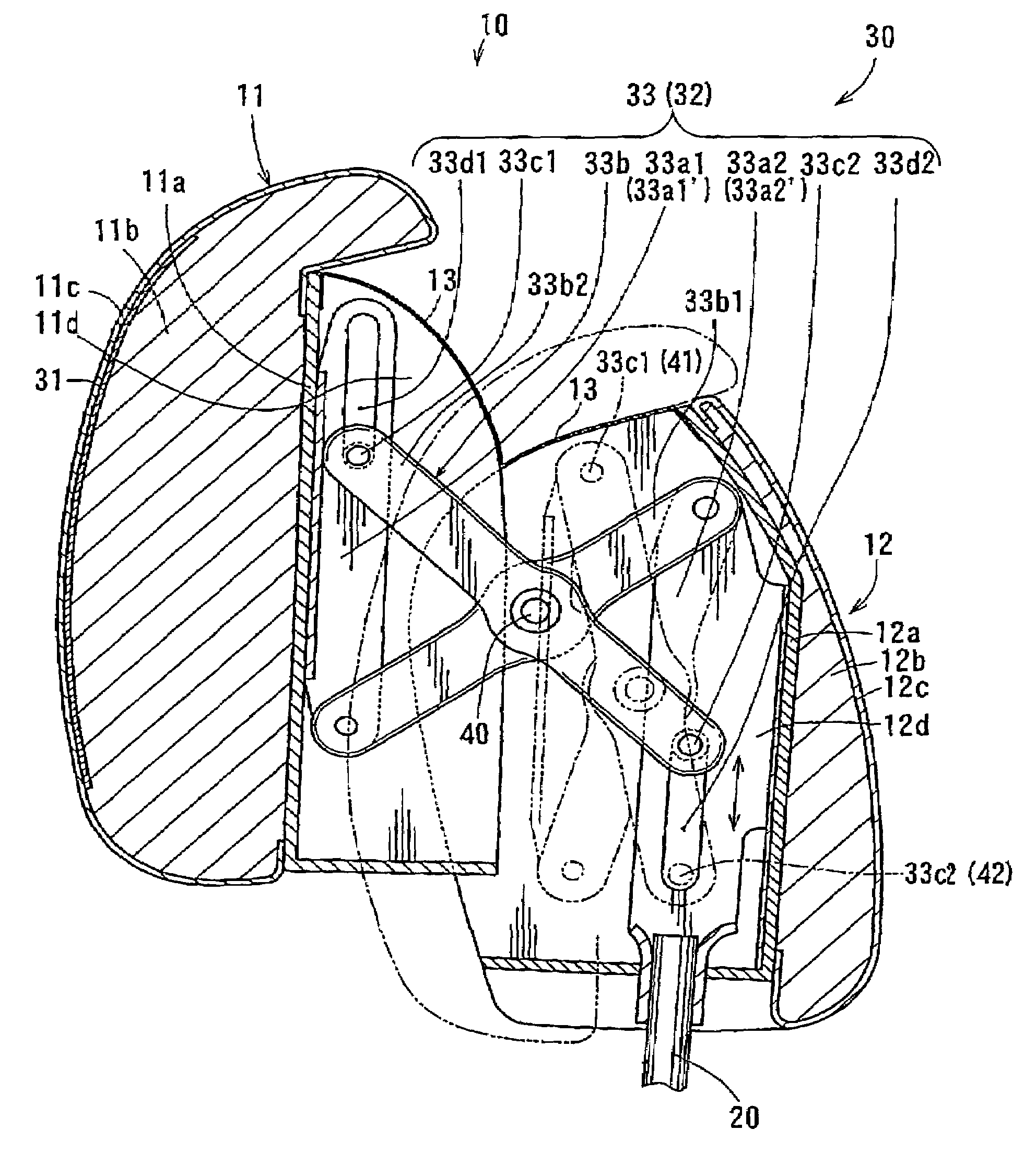
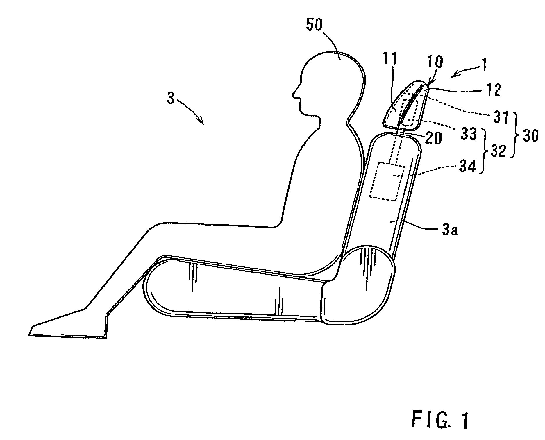
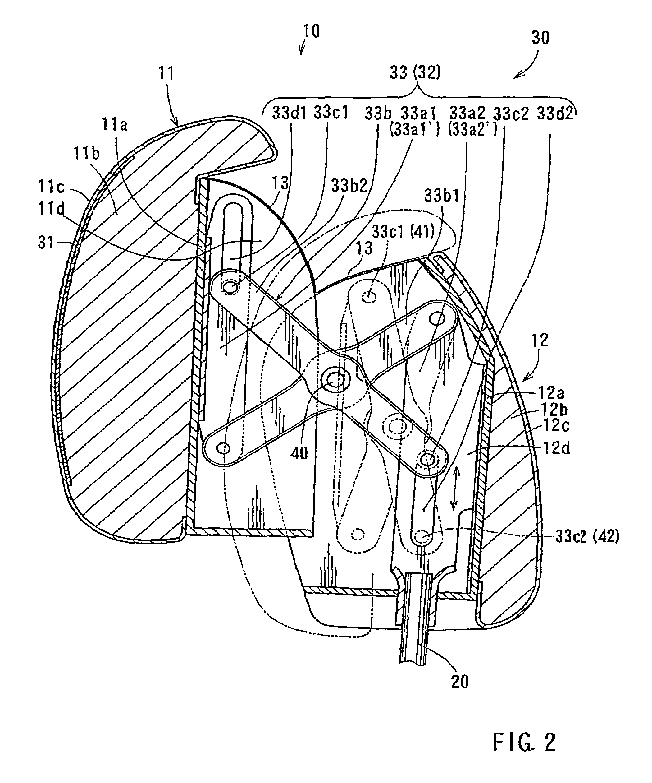
[0027]A detailed representative embodiment of the present teachings is shown in FIG. 1 to FIG. 13.

[0028]As best shown in FIGS. 1, 10 ...


PUM


Abstract

A head rest of a vehicle seat may include a head support portion for supporting a head of a passenger, and a drive unit for moving the head support portion. The drive unit has a moving mechanism that is arranged and constructed to move the head support portion vertically and back and forth relative to the vehicle seat, a head detecting device provided to the head support portion so as to detect a clearance between the passenger head and the head support portion and to generate a control signal representative of the detected clearance, and a controller that can control the moving mechanism. The controller controls the moving mechanism so as to move the head support portion to a first proximity position in which the head detecting device may have a predetermined sensitivity relative to passenger head if the head support portion does not reach the first proximity position. The controller further controls the moving mechanism based on the control signal from the head detecting device so as to move the head support portion to a second proximity position which corresponds to an optimal proximity position relative to the passenger head.

Description

BACKGROUND OF THE INVENTION[0001]1. Field of the Invention[0002]The present invention relates to head rests of vehicle seats. More particularly, the present invention relates to head rests of vehicle seats that can increase restraint performance for the heads of passengers when a vehicle collision is sensed or predicted.[0003]2. Description of the Related Art[0004]A head rest of a vehicle seat that can be appropriately positioned relative to a head of a passenger is already known. Such a head rest (an active head rest) can increase restraint performance for the passenger head when a vehicle collision is sensed or predicted. The head rest is taught, for example, by U.S. Pat. No. 6,402,195.[0005]In the known head rest, the head rest includes capacitance type sensors that are embedded in a main body of the head rest. The sensors are arranged and constructed to detect the position of the passenger head. Also, the head rest main body is constructed to move vertically (up and down) toward...

Claims


Application Information

Patent Timeline
Patent Type & Authority Patents(United States)
IPC IPC(8): B60N2/42B60N2/48
CPCB60N2/482B60N2/4829B60N2/485B60N2/4852B60N2/821B60N2/829B60N2/85B60N2/853
Inventor AKAIKE, FUMITOSHINISHIMURA, SEIYAYAJIMA, FUMIOMISAKI, NOBUMASA
Owner TOYOTA BOSHOKU KK
Why Eureka
Try Eureka