Electrical connector assembly

a technology of electrical connectors and connector assemblies, applied in the direction of coupling device details, coupling device connections, electric discharge lamps, etc., can solve the problems of damage to the insulation housing of the connector assembly, and achieve the effect of enhancing the mating for

Inactive Publication Date: 2009-02-03
HON HAI PRECISION IND CO LTD
View PDF5 Cites 25 Cited by
  • Summary
  • Abstract
  • Description
  • Claims
  • Application Information

AI Technical Summary

Benefits of technology

[0007]An object of the present invention is to provide a connector assembly with retainers which can enhance mating force.

Problems solved by technology

However, the retainers are respectively disposed out of two lateral ends of the plug connector and the receptacle connector, so during the plug connector mating with the receptacle connector, the mating portions of the retainers may distort along a longitudinal direction, which will influence an interferential force between the engaging retainers, and insulting housings of the connector assembly may be damaged by the retainers if user inserts the first connector by unbalanced force.

Method used


Image

  • Electrical connector assembly
  • Electrical connector assembly
  • Electrical connector assembly

Examples


Embodiment Construction

[0015]Reference will now be made in detail to the preferred embodiment of the present invention.

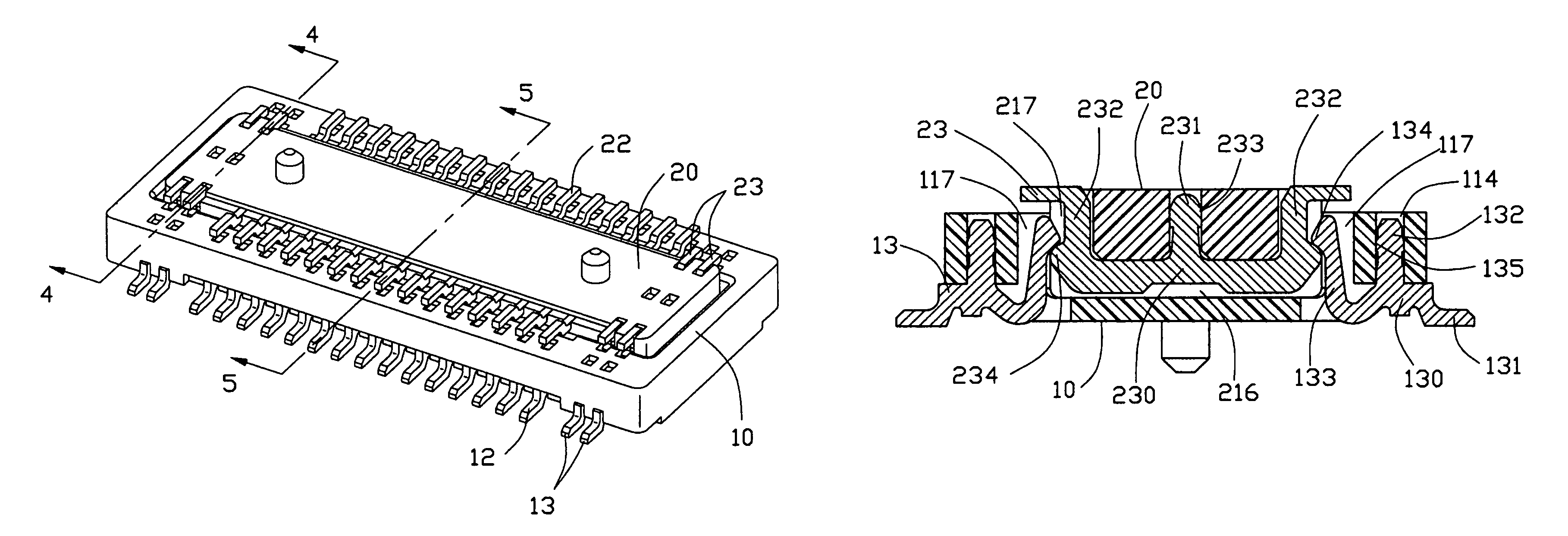
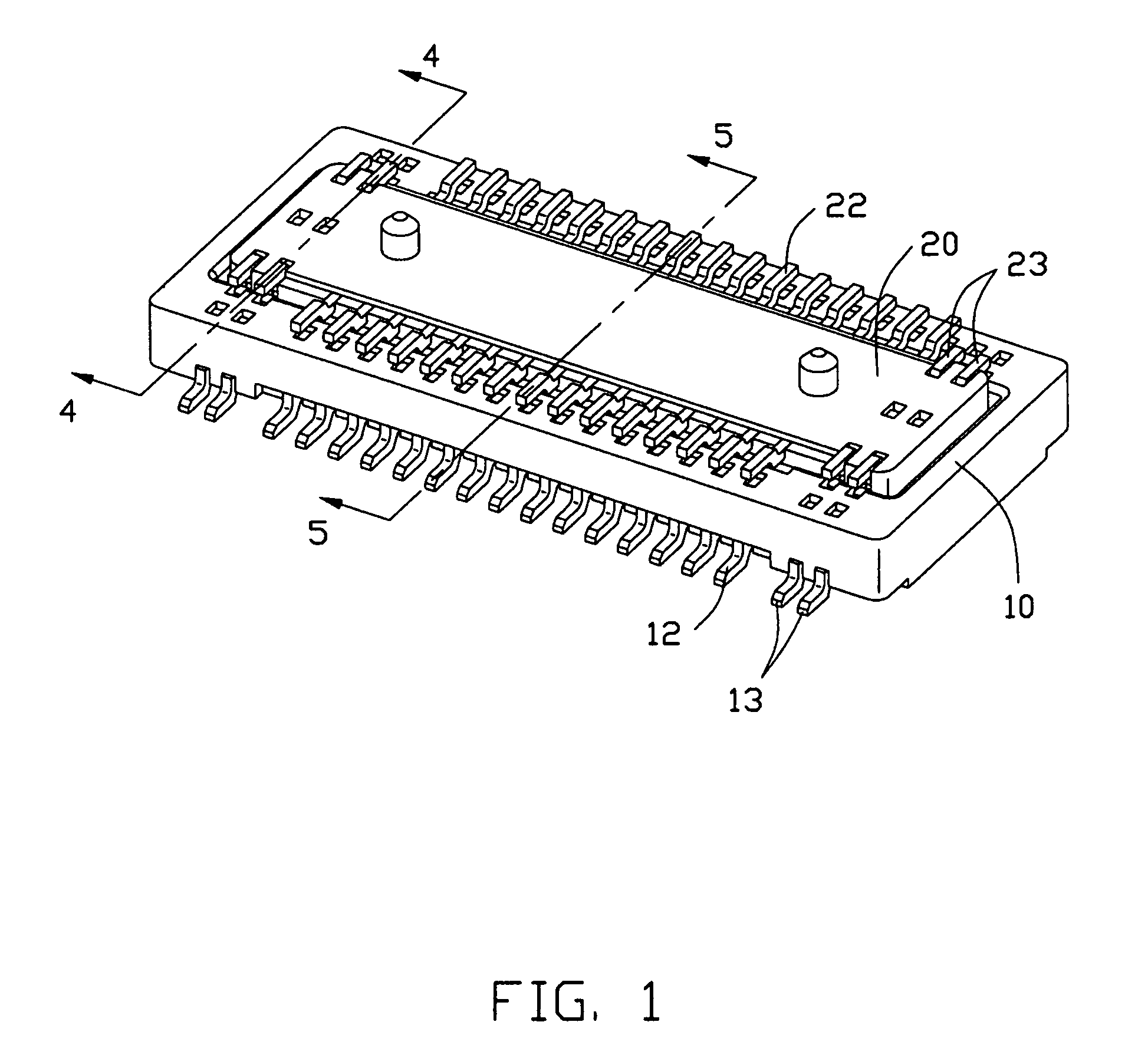
[0016]Referring to FIG. 1, the electrical connector assembly comprise a first connector 10 and a second connector 20 respectively mounted to a print circuit board (not shown).

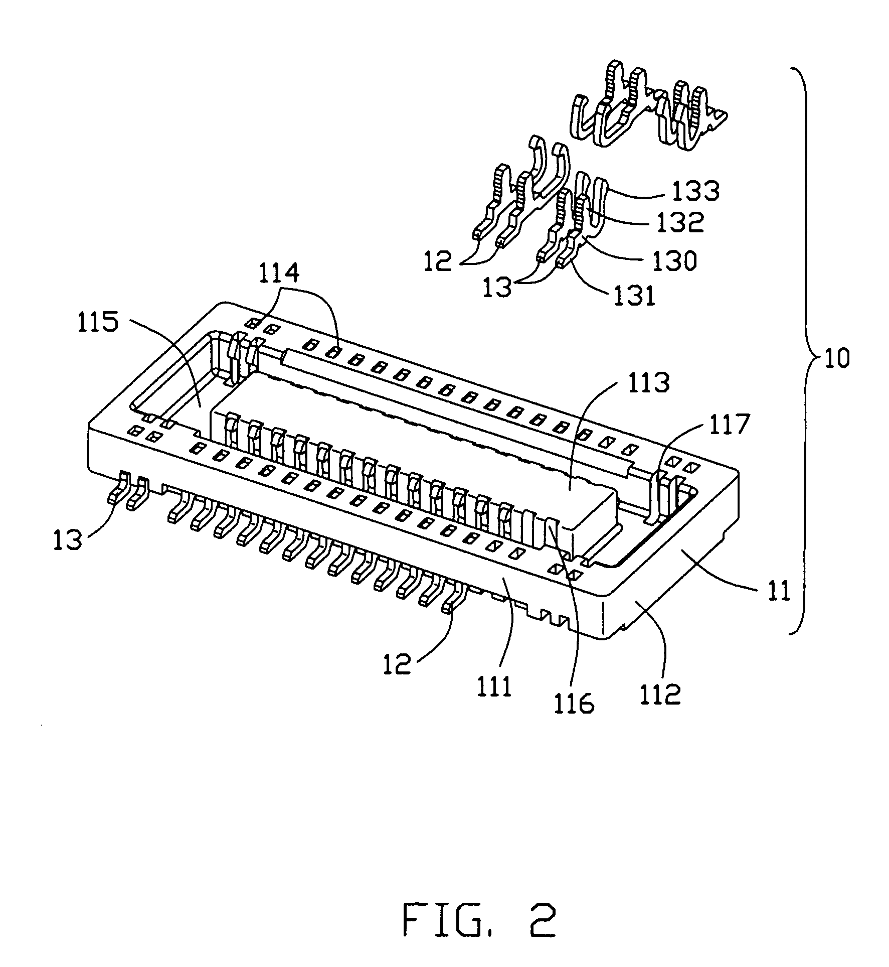
[0017]Referring to FIGS. 2 and 5, the first connector 10 comprises a first housing 11, a plurality of first contacts 12 received in the first housing 11 and a pair of first retainers 13 assembled on two opposed lateral ends of the first housing 11. The first housing 11 is a longitudinal insulating housing and has a peripheral wall (not labeled), which comprises a pair of longitudinal sidewalls 111 and a pair of transverse end walls 112. Each sidewall 111 defines a plurality of holes 114 passing through a top and a bottom surfaces thereof and a plurality of first slots 117 near the two opposed ends of the first housing 11. The first housing 1 is formed with a mating portion 113 extending from bottom of the first housi...


PUM


Abstract

An electrical connector assembly comprises a first connector having a first housing and a first retainer and a second connector having a second housing and a second retainer. The first retainer and the second retainer respectively retained on two opposed end of the first housing and the second housing. The second retainer is in an M-shaped and assembles to the second housing from a top surface of the second housing. The second retainer has two contacting arms for engaging with the first retainer.

Description

BACKGROUND OF THE INVENTION[0001]1. Field of the Invention[0002]The present invention relates to a board to board connector assembly.[0003]2. Description of Related Art[0004]A board to board connector is used to electrically link two print circuit boards to transmit electrical signals. Such a board to board connector usually has a pair of retainer members respectively assembled on opposed ends thereof, the retainer member has a soldering portion for being soldered to a print circuit board to reliably mount the board to board connector to the print circuit board.[0005]U.S. Pat. No. 6,645,005 discloses a board-to-board connector assembly having a plug connector and a receptacle connector, both the plug and the receptacle connectors have a pair of retainer members on opposed ends thereof for being soldered to a print circuit board, respectively, and each retainer member has a mating portion with a clasping portion. When the plug connector mates with the receptacle connector, the retain...

Claims


Application Information

Patent Timeline
Patent Type & Authority Patents(United States)
IPC IPC(8): H01R12/00H01R12/71
CPCH01R12/716H01R13/6275H01R12/73
Inventor SHIU, GUO-JIUN
Owner HON HAI PRECISION IND CO LTD
Why Eureka
Try Eureka