
Adaptive modulation based on signal quality

a signal quality and adaptive modulation technology, applied in the direction of transmission monitoring, frequency-division multiplex, instruments, etc., can solve the problems of deterioration of noise characteristics, inferior error correction capability, and deterioration of propagation paths at data retransmission time, so as to suppress the useless radio communication resources and improve transmission efficiency.

Active Publication Date: 2009-02-03
SONY CORP
View PDF17 Cites 19 Cited by
  • Summary
  • Abstract
  • Description
  • Claims
  • Application Information

AI Technical Summary

Benefits of technology

[0090]The present invention is made in view of the above aspect. Therefore, it is an object of the present invention to propose a solution in which a transmission parameter is controlled depending on the received signal quality at the terminal, so that a retransmission achieving no gain is reduced and useless radio communication resources are suppressed, whereby transmission efficiency can be improved.

Problems solved by technology

Therefore, the error correction capability is inferior to the case in which the data is coded at the coding rate of R=½ but a large amount of data can be transmitted.
However, since the modulation system of the 16QAM has a smaller intersymbol distance than the modulation system of the QPSK, the noise characteristic is to be deteriorated.
In the actual practice, however, there can be brought about a situation in which the propagation path is deteriorated at the data retransmission time as compared with at the initial data transmission time.
In such a situation, there can be taken place in which synthesizing the data of retransmission with data of a previous step does not bring an improvement in the transmission efficiency (i.e., no gain can be obtained by synthesizing the data of the retransmission).
This fact follows that the data of retransmission is transmitted by using an excessive energy, and resultantly the radio communication resources are to be consumed uselessly.

Method used


Image

  • Adaptive modulation based on signal quality
  • Adaptive modulation based on signal quality
  • Adaptive modulation based on signal quality

Examples


second embodiment

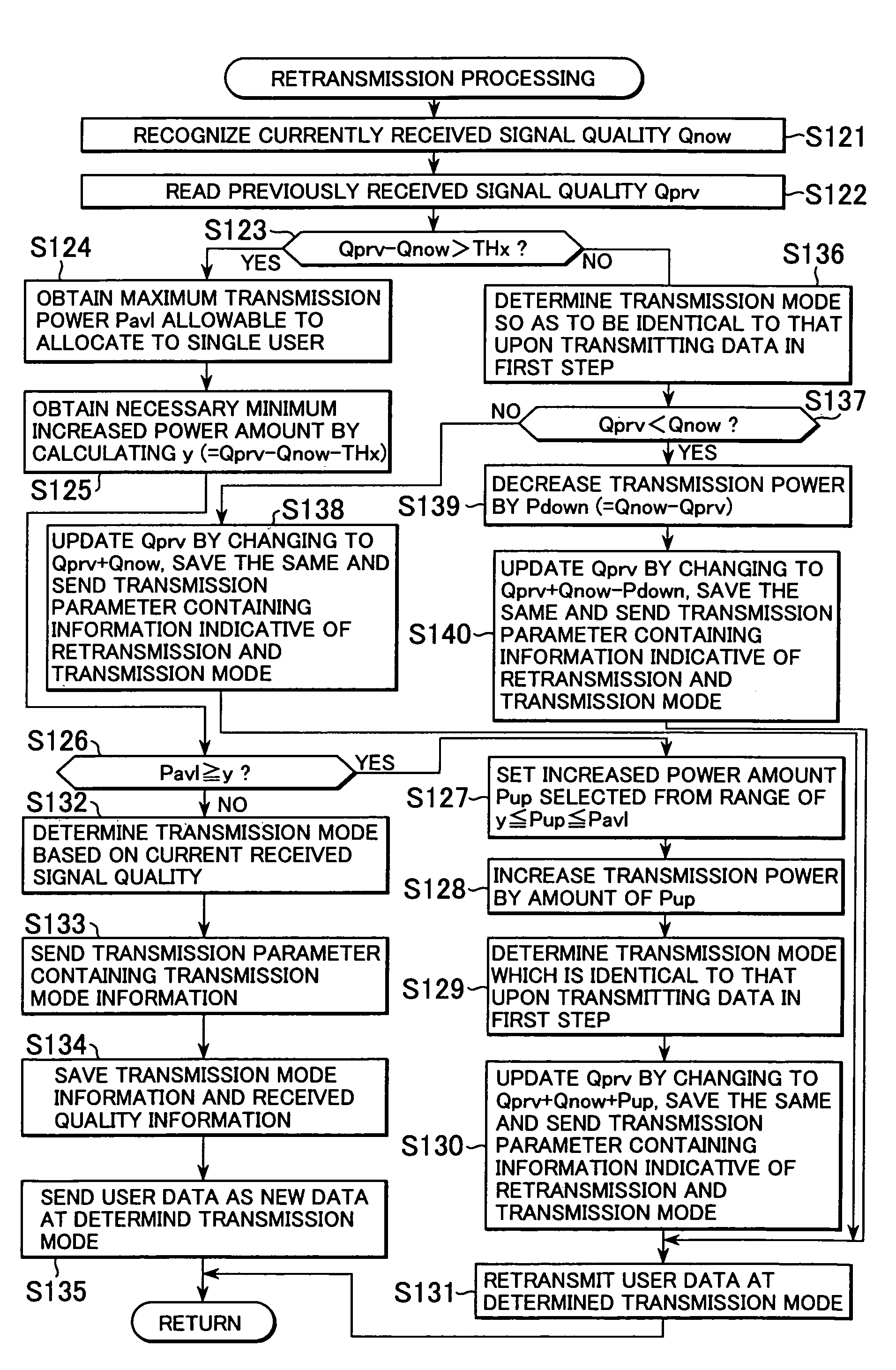
[0203]FIG. 12 is a flowchart for illustrating the retransmission carried out at step S20 shown in FIG. 10.

[0204]In the embodiment of FIG. 11, the terminal accumulates the received signal quality information upon respective data transmission operations of from the first user data transmission (the initial user data transmission) to the previous user data retransmission, whereby estimation is made on the received signal quality upon synthesizing the data of retransmission and the user data received in the previous step. In the embodiment of FIG. 12, the received signal quality upon transmitting the data in the first time is directly utilized as an estimated value of the received signal quality at the terminal.

[0205]In the embodiment of FIG. 11, at step S40, the previous received signal quality Qprv is updated by calculating the equation Qprv=Qprv+Qnow+Pup. Alternatively, at step S47, the previous received signal quality is updated by calculating the equation Qprv=Qprv+Qnow. However, i...

third embodiment

[0212]Next, FIG. 13 is a flowchart showing the retransmission carried out at step S20 of FIG. 10.

[0213]While in the embodiments of FIGS. 11 and 12 control is made on the transmission power of the downlink data channel of the transmission parameter upon retrying transmission based on the received signal quality Qprv−Qnow, in the embodiment of FIG. 13, control is made on the transmission mode of the transmission parameter upon retrying transmission based on the received signal quality difference Qprv−Qnow.

[0214]In the embodiment of FIG. 13, processing is carried out from step S91 to S93 in a manner similar to those carried out in steps from S31 to S33.

[0215]At step S93 corresponding to step S33, if it is determined that the received signal quality difference Qprv−Qnow is larger than the threshold value THx and hence the current received signal quality Qnow is deteriorated relative to the previous received signal quality Qprv, the mode determining unit 111 supplies information indicati...

fourth embodiment

[0238]FIG. 14 is a flowchart showing the retransmission processing at step S20 of FIG. 10.

[0239]In the embodiments of FIGS. 11 and 12 the transmission power upon retransmitting data is controlled based on the received signal quality Qprv−Qnow, and in the embodiment of FIG. 13 the transmission mode upon retransmitting data is controlled based on the received signal quality Qprv−Qnow. However, in the embodiment of FIG. 14 both of the transmission power upon retransmitting data and the transmission mode upon retransmitting data can be controlled based on the received signal quality Qprv−Qnow.

[0240]Now the retransmission processing of FIGS. 11 and 12 is referred to as retransmission at a changed transmission power and the retransmission processing of FIG. 13 is referred to as retransmission at a changed transmission mode. In the embodiment of FIG. 14, initially, at step S111, the control unit 112 examines whether the base station can afford to allocate additional resources or not.

[0241]...


PUM


Abstract

An apparatus and a method for improving the transmission efficiency when a retransmission of a communication is attained based on a Hybrid-ARQ (Automatic repeat ReQuest) system. A mode determining unit of a base station executes calculations to obtain a received signal quality difference between a received signal quality at the current stage and that of a past stage at a terminal, and supplies the received signal quality difference to a control unit. The control unit controls a power setting unit based on the received signal quality difference to control a transmission power of a signal transmitted from an adaptive coding and modulation unit. The present invention can be applied to a base station of a portable telephone communication network.

Description

TECHNICAL FIELD[0001]The present invention relates to a transmission apparatus and a method for controlling signal transmission. In more particularly, the present invention relates to a transmission apparatus and a method for controlling signal transmission for use in a communication system for portable telephones or the like, wherein transmission power, modulation systems, coding systems and packet synthesizing method are properly selected in accordance with the received information which are useful for adaptive modulation and coding transmission upon signal retransmission, and accordingly, a packet transmission can be achieved in more effective manner. In other words, the present invention relates to a transmission apparatus and a method for controlling signal transmission, and in more particularly, the present invention relates to a transmission apparatus and a method for controlling signal transmission that are able to effectively transmit data from a base station to a terminal ...

Claims


Application Information

Patent Timeline
Patent Type & Authority Patents(United States)
IPC IPC(8): H04L1/00H04B7/005
CPCH04L1/0003H04L1/0009H04L1/0015H04L1/0025H04L1/1809H04L1/1867H04W52/48H04W52/50H04L1/18
Inventor ITOH, KATSUTOSHI
Owner SONY CORP
Learn More