Transceiver test module employing an optical wrap

Inactive Publication Date: 2009-02-03
INT BUSINESS MASCH CORP
View PDF9 Cites 1 Cited by
  • Summary
  • Abstract
  • Description
  • Claims
  • Application Information

AI Technical Summary

Problems solved by technology

Optical transceivers typically have no direct external indication as to the speed capability of the unit, and have no display mechanism to indicate whether the unit is defective.

Method used


Image

  • Transceiver test module employing an optical wrap
  • Transceiver test module employing an optical wrap
  • Transceiver test module employing an optical wrap

Examples


Embodiment Construction

[0013]This invention is described in preferred embodiments in the following description with reference to the Figures, in which like numbers represent the same or similar elements. While this invention is described in terms of the best mode for achieving this invention's objectives, it will be appreciated by those skilled in the art that variations may be accomplished in view of these teachings without deviating from the spirit or scope of the invention.

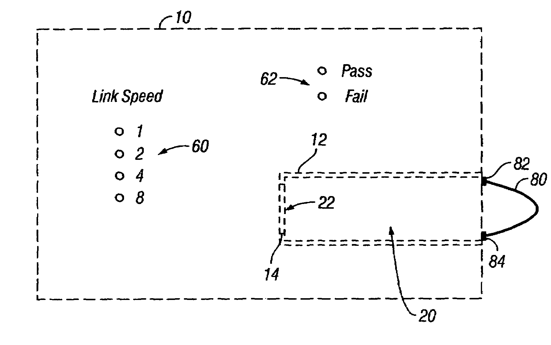
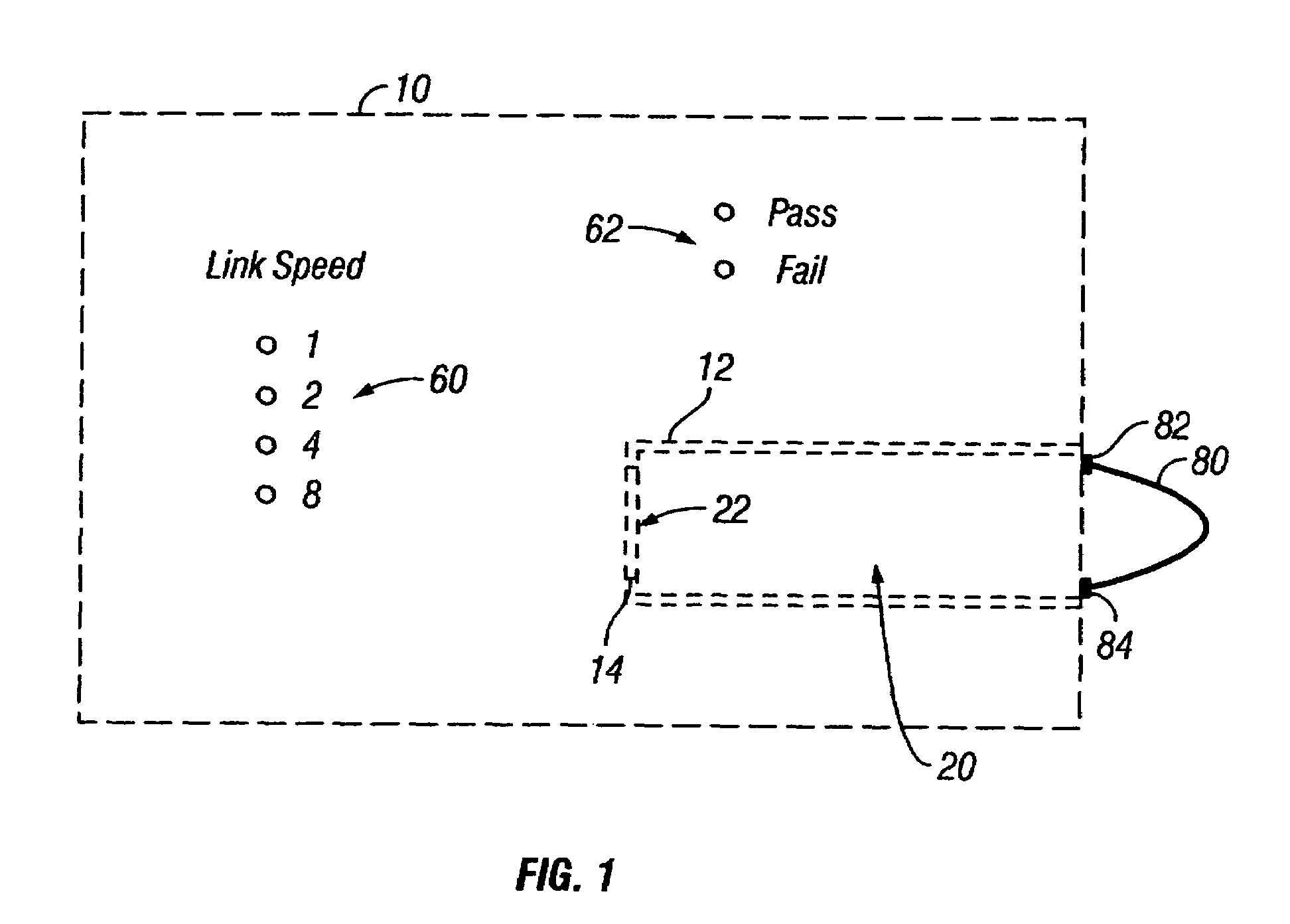
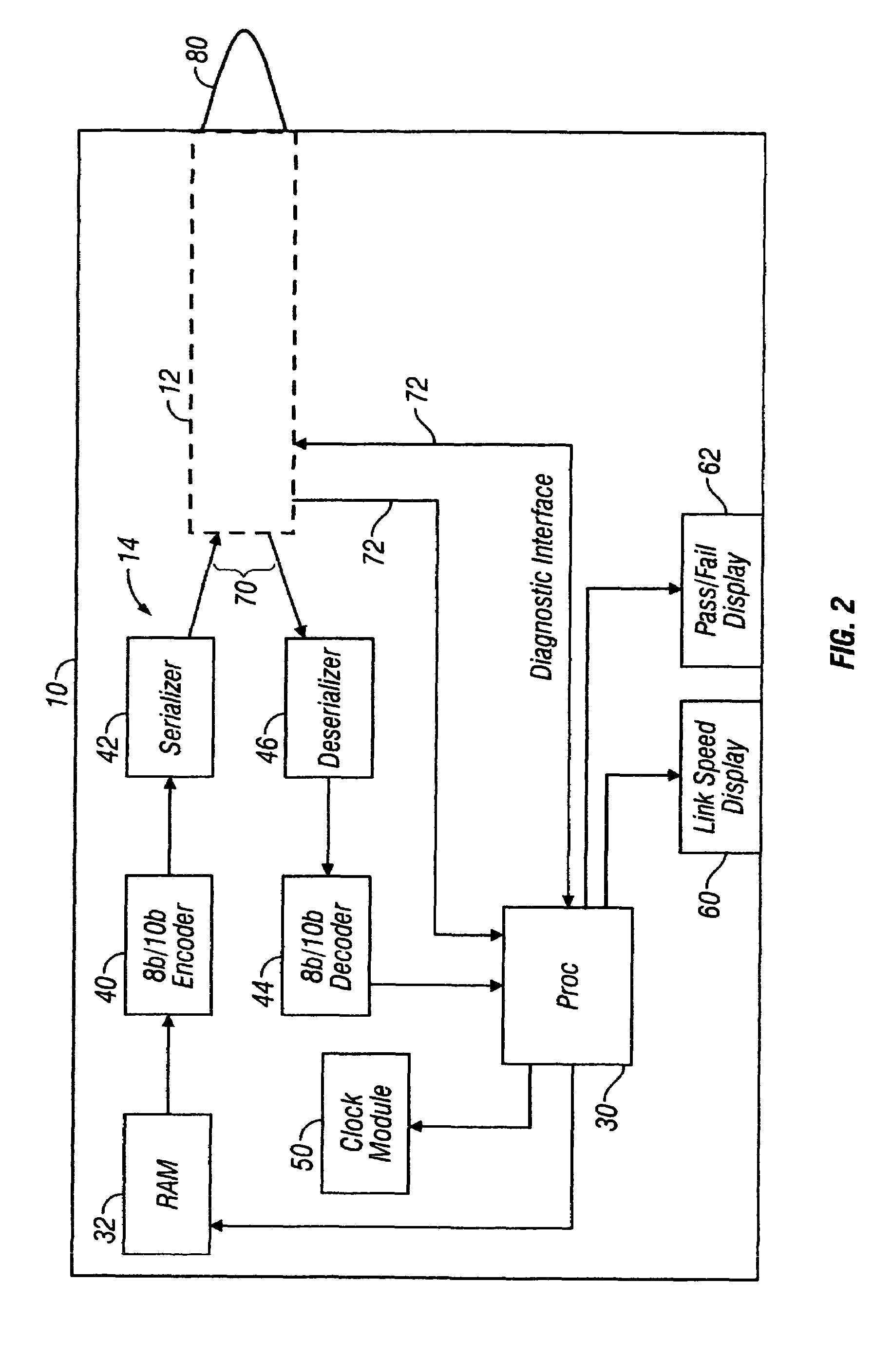
[0014]Referring to FIGS. 1 and 2, an embodiment of a transceiver test module 10 is illustrated having a cage 12 with a plug interface 14 for supporting an optical transceiver 20. A plug input / output interface 22 of the optical transceiver 20 plugs into the interface 14 when the optical transceiver is loaded into the transceiver test module. The plug interface 14 additionally comprises a power connection to power the optical transceiver 20.

[0015]A processor system comprises a processor 30 and memory 32 for operating the transceiver te...


PUM


Abstract

A transceiver test module and method for testing an optical transceiver. An optical wrap interconnects the optical transmitter and optical receiver of an optical transceiver. A processor system reads information from an optical transceiver; provides a signal to the optical transceiver to operate the optical transceiver to transmit a signal at the optical transmitter, which is received via the optical wrap; detects diagnostic information from the optical transceiver for errors of the optical transceiver; and determines the rated speed of the optical transceiver from the read information. Operation of the optical transceiver at the rated speed is verified by the diagnostic information.

Description

FIELD OF THE INVENTION[0001]This invention relates to optical transceivers, and, more particularly, to testing optical transceivers.BACKGROUND OF THE INVENTION[0002]Optical transceivers typically have no direct external indication as to the speed capability of the unit, and have no display mechanism to indicate whether the unit is defective. With regard to speed capability, various units from the same manufacturer may appear identical or nearly so, and the only way to differentiate between, for example, a 2 Gb (gigabyte) transceiver and a 4 Gb transceiver, is to have the two different part numbers memorized. With regard to viability, one method to make a determination whether a transceiver is viable is to exchange a suspect transceiver with a known good one and try communication using the known good transceiver.SUMMARY OF THE INVENTION[0003]A transceiver test module and method for testing an optical transceiver. An optical wrap interconnects the optical transmitter and optical recei...

Claims


Application Information

Patent Timeline
Patent Type & Authority Patents(United States)
IPC IPC(8): H04B10/08H04B17/00
CPCH04B10/0731
Inventor AIN, JONATHAN WADEKLEIN, CRAIG ANTHONY
Owner INT BUSINESS MASCH CORP
Why Eureka
Try Eureka