Gun type continuous clip ejecting apparatus

Inactive Publication Date: 2009-02-10
LEE YONG WOO
View PDF9 Cites 9 Cited by
  • Summary
  • Abstract
  • Description
  • Claims
  • Application Information

AI Technical Summary

Benefits of technology

[0006]Therefore, the present invention has been made in view of the above mentioned problems, and an object of the invention is to provide a gun type continuous clip ejecting

Problems solved by technology

However, it is inconvenient to use.
Accordingly, there are several disadvantages that a big

Method used


Image

  • Gun type continuous clip ejecting apparatus
  • Gun type continuous clip ejecting apparatus
  • Gun type continuous clip ejecting apparatus

Examples


Embodiment Construction

)

[0017]Now, the present invention will be described in detail with reference to the annexed drawings.

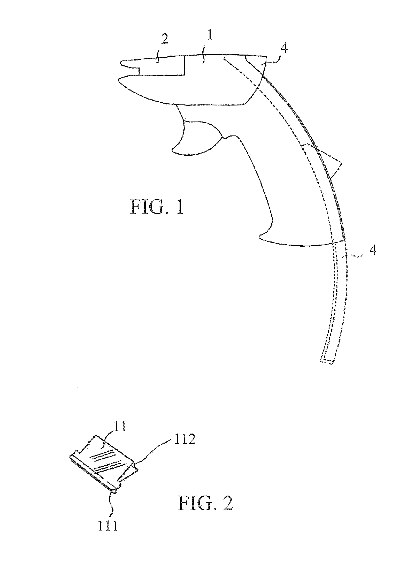
[0018]FIG. 1 is a side view schematically illustrating a construction of a gun type continuous clip ejecting apparatus according to an embodiment of the present invention.

[0019]FIG. 2 is a perspective view schematically illustrating a clip embedded within a gun type continuous clip ejecting apparatus according to an embodiment of the present invention.

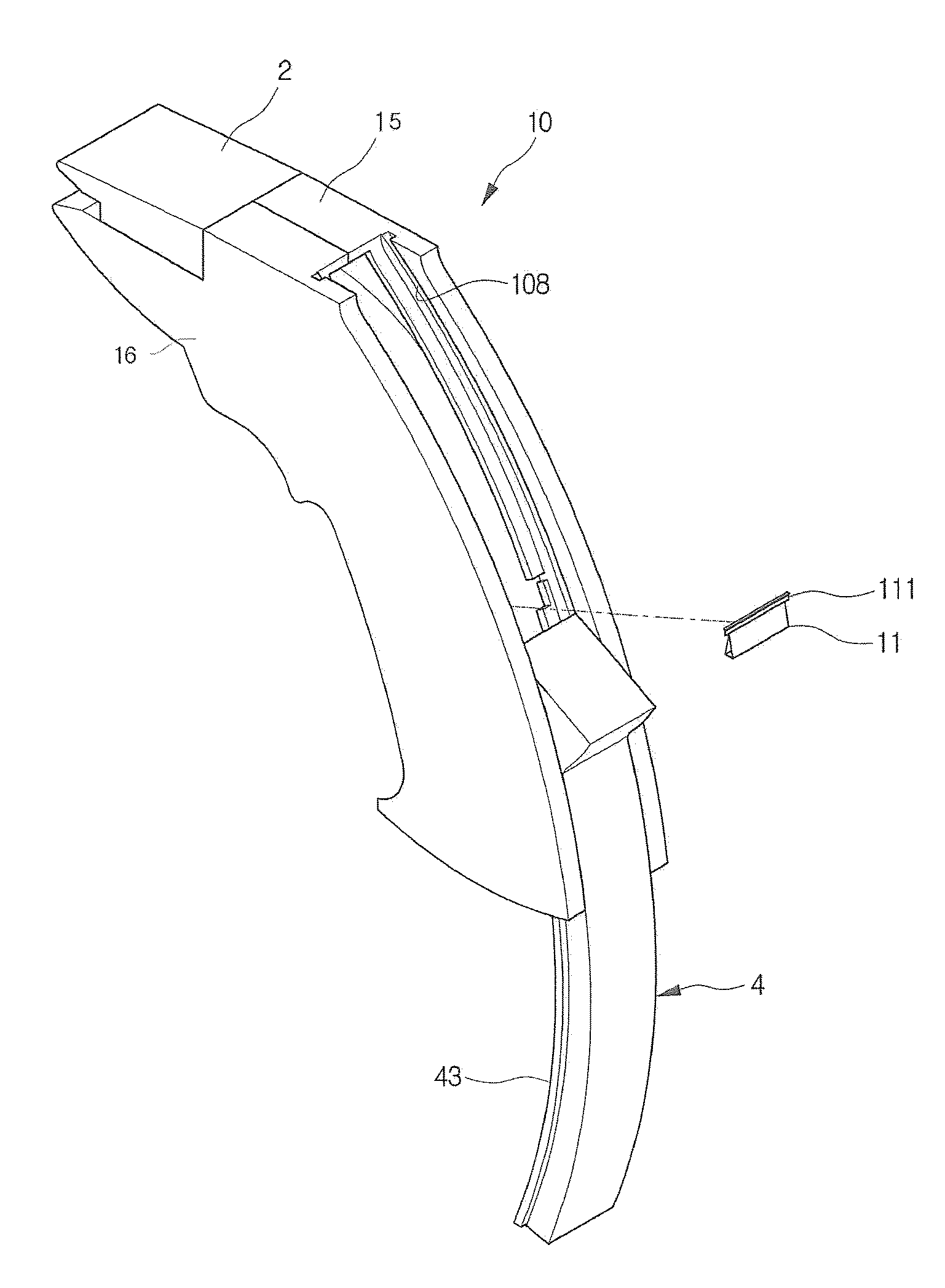
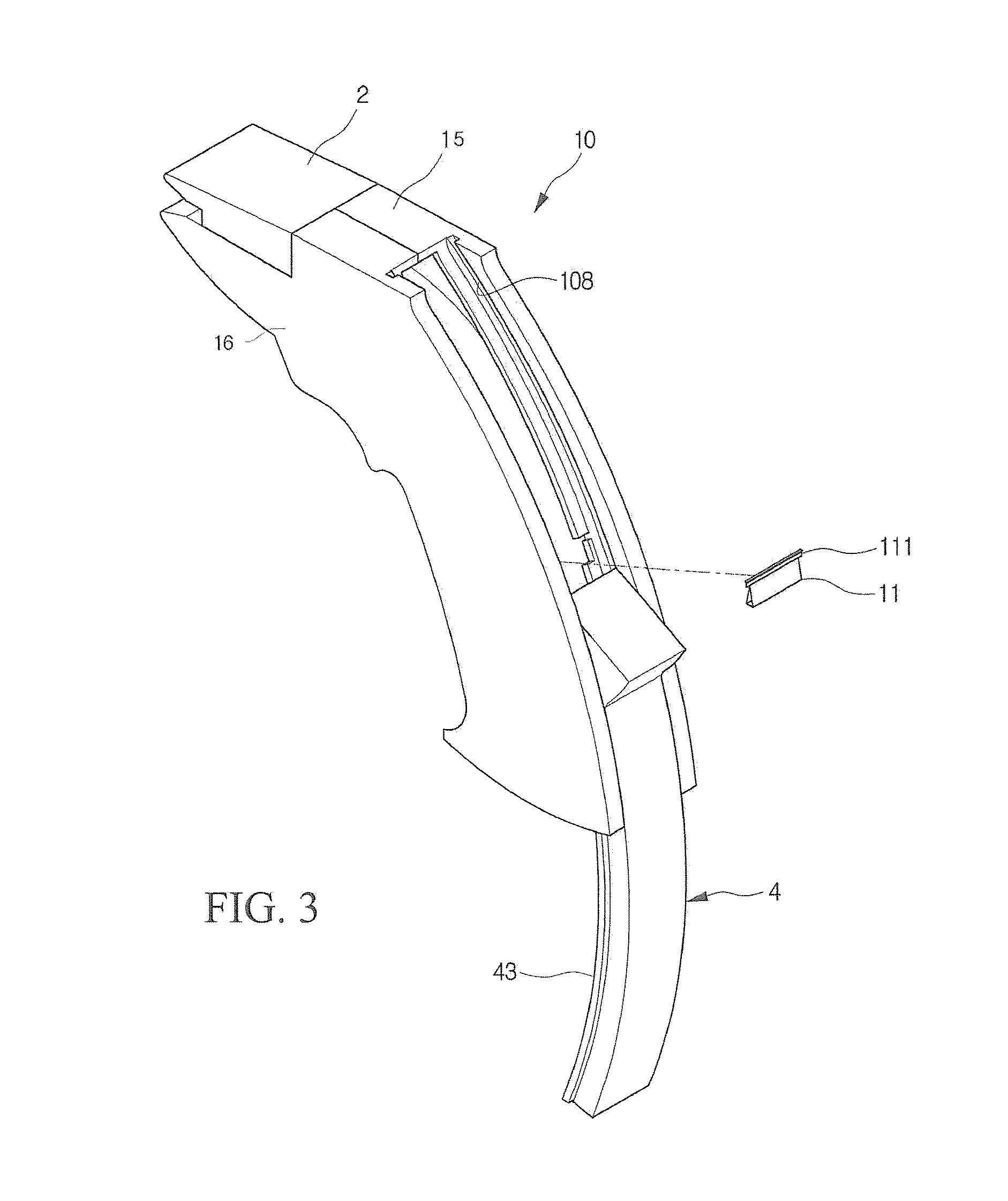
[0020]FIG. 3 is a perspective view schematically illustrating a gun type continuous clip ejecting apparatus according to an embodiment of the present invention.

[0021]FIGS. 4 and 5 are partially exploded perspective views of FIG. 3, and FIG. 6 is a side cross-sectional view of FIG. 1.

[0022]As shown in FIGS. 1 to 6, a gun type continuous clip ejecting apparatus is to bind documents through clips 11 mounted therein.

[0023]The gun type continuous clip ejecting apparatus 10 comprises a body 1 including bodies 15 and 16 symmetrically combined ...


PUM


Abstract

Disclosed is a gun type continuous clip ejecting apparatus. The gun type continuous clip ejecting apparatus includes a body including bodies symmetrically combined by each other with a curved shape and a clip guide groove therein; a cover inserted into the upper front end of the body; a slider installed slidably along a guide groove formed within the body; a clip loading push rod in which protrusions are formed at an end thereof and hooked to the hook of the slider, a hook is protruded upwardly at the other end thereof and protrusions are protruded at sides thereof; a tension spring in which an end thereof is hooked to the hook of the clip loading push rod and the other end thereof is pulled upwardly and fixed to the upper inside surface of the slider; a discharge push rod; a tension spring; and a trigger rotatably fixed to a bottom side of the body by a hinge shaft and including upper hooking protrusions contacted with a bottom end between both sides of the discharge push rod.

Description

BACKGROUND OF THE INVENTION[0001]1. Field of the Invention[0002]The present invention relates to a gun type continuous clip ejecting apparatus, and more particularly to a gun type continuous clip ejecting apparatus in which the clip ejecting apparatus is formed by a gun shape and clips are continuously ejected whenever a trigger of the apparatus is pulled, thereby being used conveniently and rapidly.[0003]2. Description of the Related Art[0004]Generally, a clip ejecting apparatus with a push or press manner have been used mainly in a conventional art. However, it is inconvenient to use. More specifically, when using the convention clip ejecting apparatus (herein-after, described as a dispenser), the dispenser is inclined toward the front thereof in order to reach clips to the front and thereafter a pressing rod of the dispenser is pushed forwardly by a thumb of a user contacted thereon, so that the clips are pushed forwardly. The above procedures must be performed repeatedly wheneve...

Claims


Application Information

Patent Timeline
IPC IPC(8): B23Q7/10B23P11/00
CPCB25B31/00Y10T29/53504Y10T29/53783Y10T29/53487Y10T29/53909B25C5/00B25C5/06B25C5/11
Inventor LEE, YONG WOO
Owner LEE YONG WOO
Why Eureka
Try Eureka