Resin boots for constant velocity universal joint

a technology of universal joints and boots, which is applied in the direction of mechanical equipment, other domestic objects, couplings, etc., can solve the problems of grease leakage, both elements are not securely welded, and grease leakage, so as to improve the operability of assembling and achieve excellent sealing

Inactive Publication Date: 2009-02-10
FUKOKU CO LTD
View PDF15 Cites 12 Cited by
  • Summary
  • Abstract
  • Description
  • Claims
  • Application Information

AI Technical Summary

Benefits of technology

[0027]According to the above aspects of the present invention, there can be provided a resin boot for constant velocity universal joint in which different thickness portions including large thickness portions and small thickness portions are welded and integrated with the inner or outer surface of the large diameter side end portion of the resin bellow by injection molding, whereby it is possible to solve the problem of the grease leakage and, at the same time, improve an assembling operability.
[0028]Further, as for the resin boot for constant velocity universal joint in which the different thickness portion including large thickness portions and small thickness portions are welded and integrated with the outer surface of the large diameter side end portion of the resin bellow by secondary molding, a contact portion of the molten material from injected at the time of secondary molding cannot be seen, with the result that an excellent sealing effect is attained and grease does not leak.

Problems solved by technology

However, when assembling the boot having the structure in FIG. 24 and FIG. 25 above in which the bellows 100 and the grommet 200 are independently formed and are fitted and assembled, there is a fear in that a grease may leak.
Further, in Japanese Unexamined Utility Model Registration Application Publication No. 2-22463 and Japanese Unexamined Patent Publication No. 2002-286048, no specific technical means is provided in integrally forming the grommet and the bellows, so the both elements are not securely welded even if they are integrally formed on the surface.
Accordingly, the portion which is expected to be integrally formed peels off, with the result that there is generated a problem such as grease leakage.

Method used


Image

  • Resin boots for constant velocity universal joint
  • Resin boots for constant velocity universal joint
  • Resin boots for constant velocity universal joint

Examples


first embodiment

[0054]A description will be given of one embodiment in accordance with the present invention with reference to the accompanying drawings. In this case, the present embodiment only shows one aspect of the present invention, and the present invention is not limited to this embodiment any more, and can be changed in design within the scope of the present invention as occasion demands.

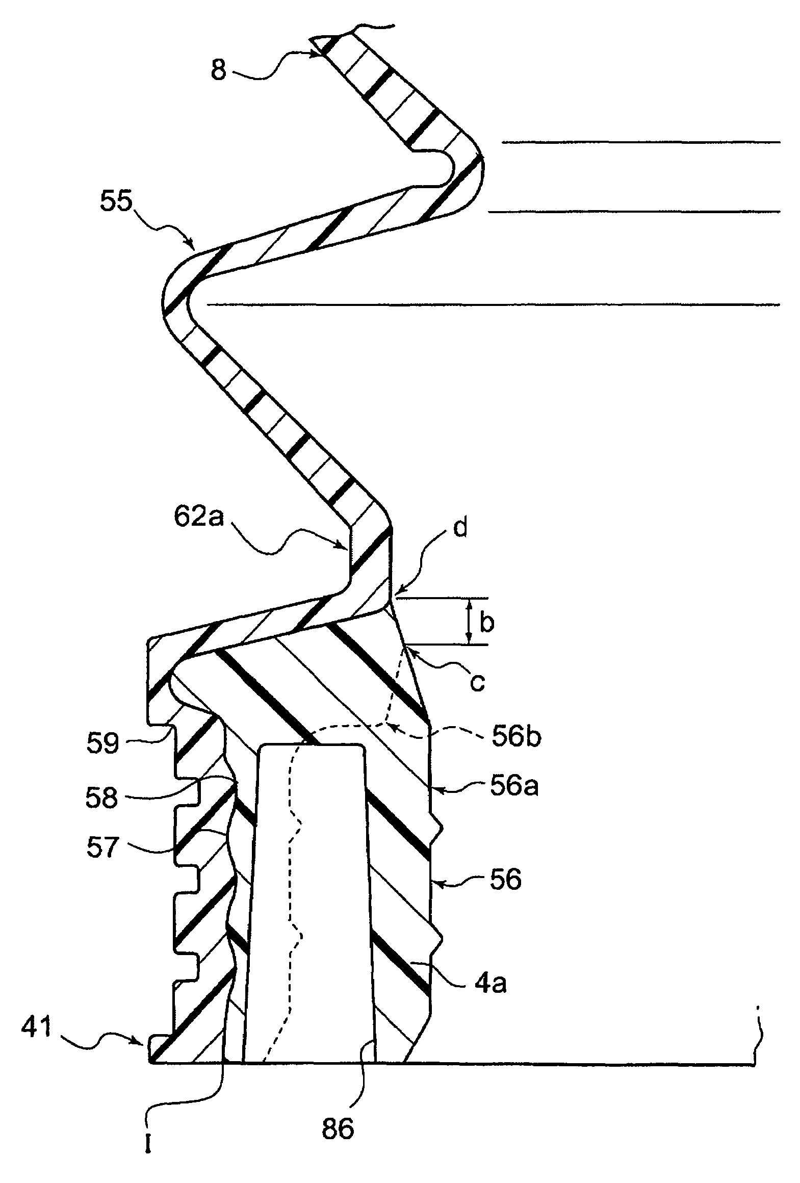
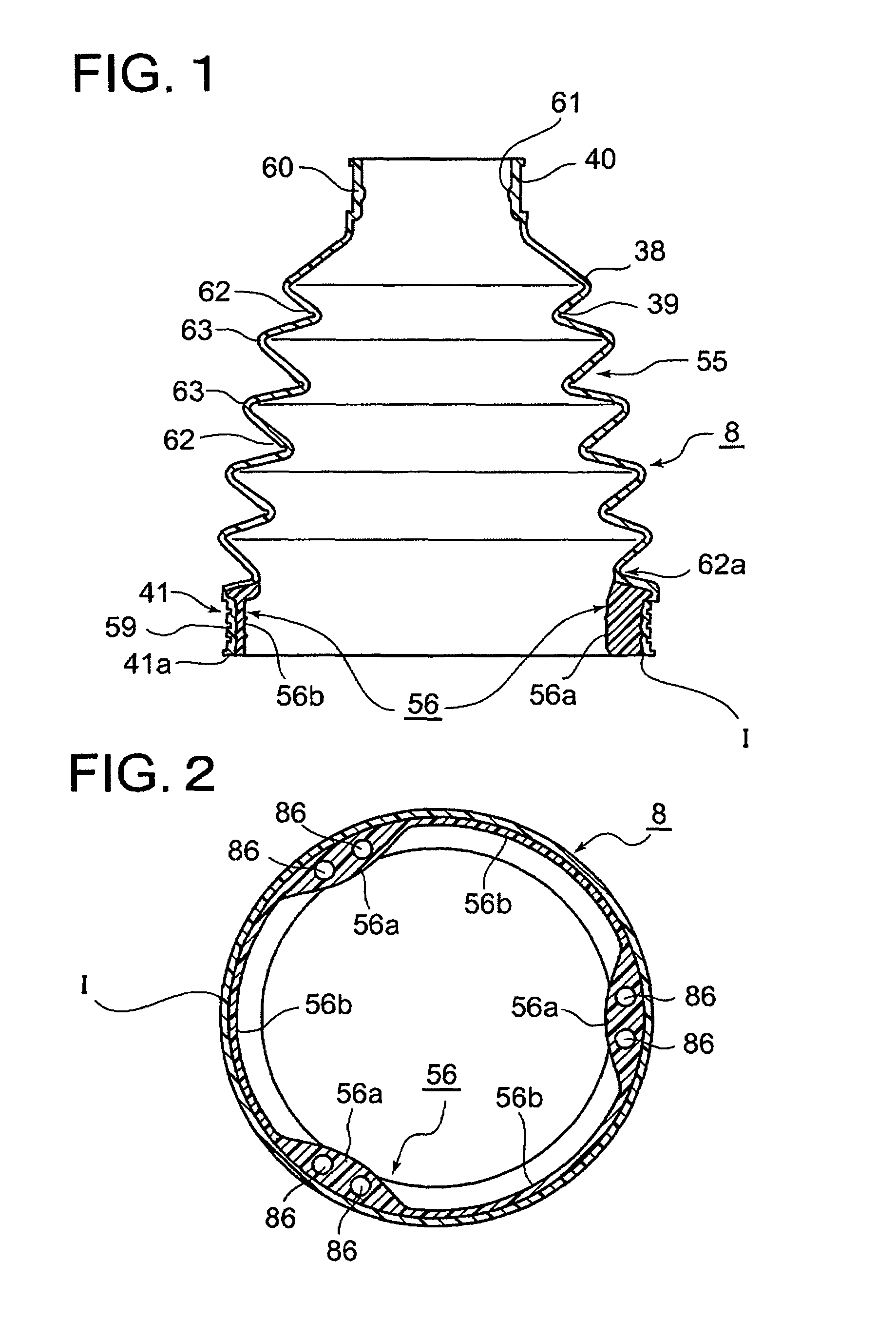
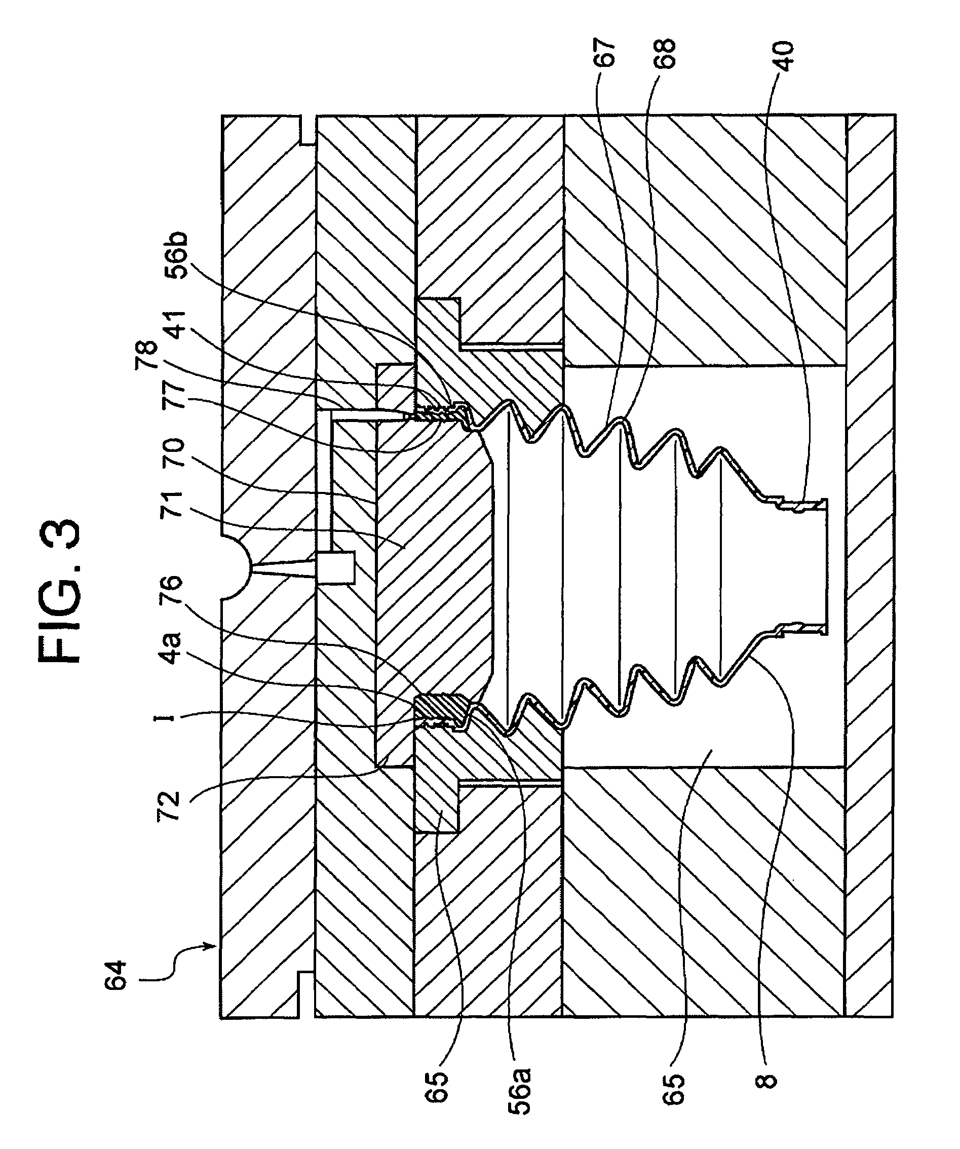
[0055]FIG. 1 is a vertical sectional view showing a resin boot for constant velocity universal joint in accordance with an embodiment of the present invention, FIG. 2 is a cross-sectional view showing the resin boot for constant velocity universal joint in accordance with the embodiment of the present invention, FIG. 3 is a simplified cross-sectional view showing the secondary molding step of this embodiment, FIG. 4 is an enlarged cross-sectional view showing a main part in FIG. 3, and FIG. 5 is an enlarged cross-sectional view showing a secondarily molded large diameter side end portion in a partly omitte...

second embodiment

[0115]In the first embodiment as described above, a different thickness portion 56 composed of large thickness portions 56a and small thickness portions 56b are welded and integrated (I) in the inner surface of a large diameter side end portion 41 of a primarily molded resin bellows 8 in accordance with a secondary molding. However, the second embodiment shown in FIGS. 19 to 22 adopted the embodiment in which a different thickness portion 560 composed of large thickness portions 560a and small thickness portions 560b are integrally injection molded in the outer surface of a large diameter side end portion 410 of a primarily molded resin bellows 800 in accordance with a secondary molding, in the purpose to achieve the same object, which will be described in detain below.

[0116]First, a resin bellows 800 which is primarily molded product, during the primary molding, forms a large diameter side end portion 410 into an approximately similar shape to that of an outer peripheral surface of...


PUM

PropertyMeasurementUnit
temperatureaaaaaaaaaa
velocityaaaaaaaaaa
diameteraaaaaaaaaa

Abstract

A resin boots for constant velocity universal joint, including: a resin bellows including an approximately conical bellows-shaped portion with its inner hollow part, a small diameter end portion communicated with an inner space of the bellows-shaped portion and arranged at one end, and a large diameter side end portion communicated with the inner space of the bellows-shaped portion and arranged at the other end; a large thickness portion formed in an inner surface of a large diameter side end portion of the resin bellows in accordance with an injection molding, protruded in the vertical direction to the center of the large diameter side end portion and arranged in the circumferential direction at regular intervals; and a small thickness portion arranged between the large thickness portions and formed thinner in the diametrical direction compared with large thickness portion.

Description

DESCRIPTION OF THE RELATED APPLICATION[0001]The present application is a CIP application of the U.S. patent application Ser. No. 10 / 396,520 which was filed on Mar. 26, 2003.BACKGROUND OF THE INVENTION[0002]1. Field of the Invention[0003]The present invention relates to a resin boot for constant velocity universal joint used in a state of being firmly fixed to an outer peripheral surface of a tripod joint, an outer periphery of which is formed in a convex-recess shape, in a constant velocity universal joint, for example, used in a drive shaft and a propeller shaft for transmitting a power from an engine of a motor vehicle to a tire.[0004]2. Description of the Related Art[0005]The tripod joint has recess portions formed in desired portions on the outer peripheral surface for various purposes such as reduction in thickness, reduction in weight and the like.[0006]In the resin boot for constant velocity universal joint used in a state of being firmly fixed to the outer peripheral surface...

Claims


Application Information

Patent Timeline
Patent Type & Authority Patents(United States)
IPC IPC(8): F16D3/84
CPCB29C45/14336F16D3/845B29L2023/18B29L2031/703Y10S464/905F16D3/2055
Inventor SUEOKA, KAZUHIKOTAKADA, YASUJI
Owner FUKOKU CO LTD
Why Eureka
Try Eureka