Display device and method of assembling the display device

a display device and display device technology, applied in the field of display device and a display device assembly method, can solve the problems of difficult alignment of holes, easy twisting and bending of the reflection portion, and drop in the uniformity ratio of reflection light, so as to improve workability

Active Publication Date: 2009-02-10
JAPAN DISPLAY INC +1
View PDF3 Cites 1 Cited by
  • Summary
  • Abstract
  • Description
  • Claims
  • Application Information

AI Technical Summary

Benefits of technology

[0014]It is an object of the present invention to provide technology capable of improving workability when support members are to be attached to a reflection plate.
[0015]It is another object of the present invention to provide technology capable of reducing damage to the support members when the support members are to be attached to the reflection plate.
[0016]It is still another object of the present invention to provide technology capable of reducing the protruding height of leg portions of the support members when the support members are to be attached to the reflection plate.

Problems solved by technology

However, when the chevron-shaped auxiliary reflection portion and the planar surface are disposed on the bottom surface of the reflection portion, as in the reflection portion of the backlight disclosed in JP-A-7-64084, it is conceivable for there to be the problem that it becomes easy for the reflection portion to twist and bend such that the uniformity ratio of reflection light drops.
However, in the case of the method shown in FIG. 17, there has been the problem that when the support member 205 is to be attached, it is difficult to align the hole in the reflection plate 202 and the leg portion 205b of the support member 205, and the workability has been poor.
For this reason, there is the problem that the attachment height becomes high when a circuit board including a circuit such as a timing controller is attached in the region where the leg portion 205b of the support member 205 protrudes, for example.

Method used


Image

  • Display device and method of assembling the display device
  • Display device and method of assembling the display device
  • Display device and method of assembling the display device

Examples


Embodiment Construction

[0049]The present invention will be described in detail below together with an embodiment with reference to the drawings.

[0050]It will be noted that, in all of the drawings for describing the embodiment, the same reference numerals will be given to members having the same functions, and redundant description thereof will be omitted.

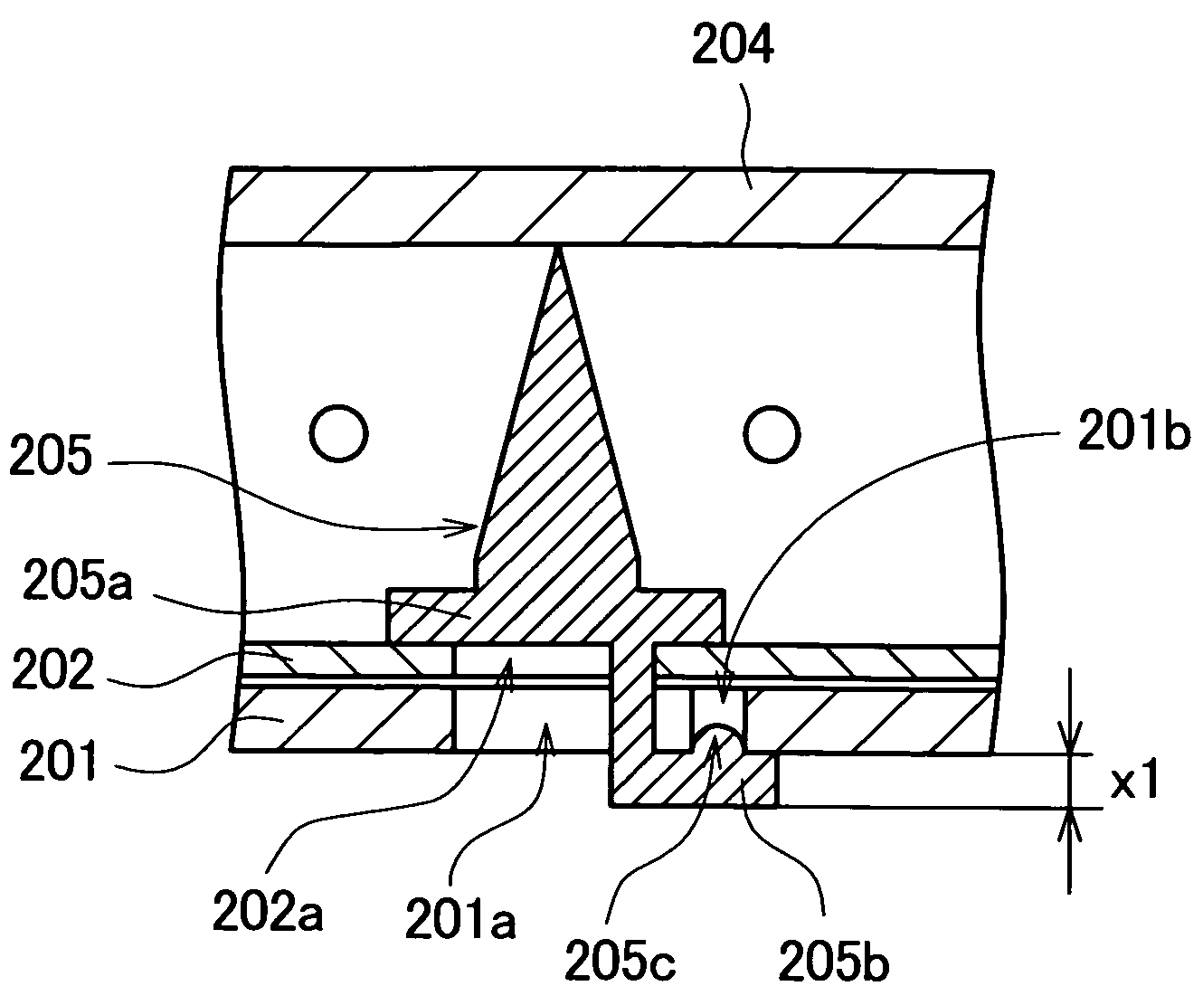
[0051]In the display device of the invention, by making a shape that the leg portion of the support member which is disposed standing on the reflection plate is bent in a direction along the standing support of the support member, the damage upon attachment is prevented and further the protruding height is reduced. Also, by sliding and fixing the support member, the workability upon attachment is improved.

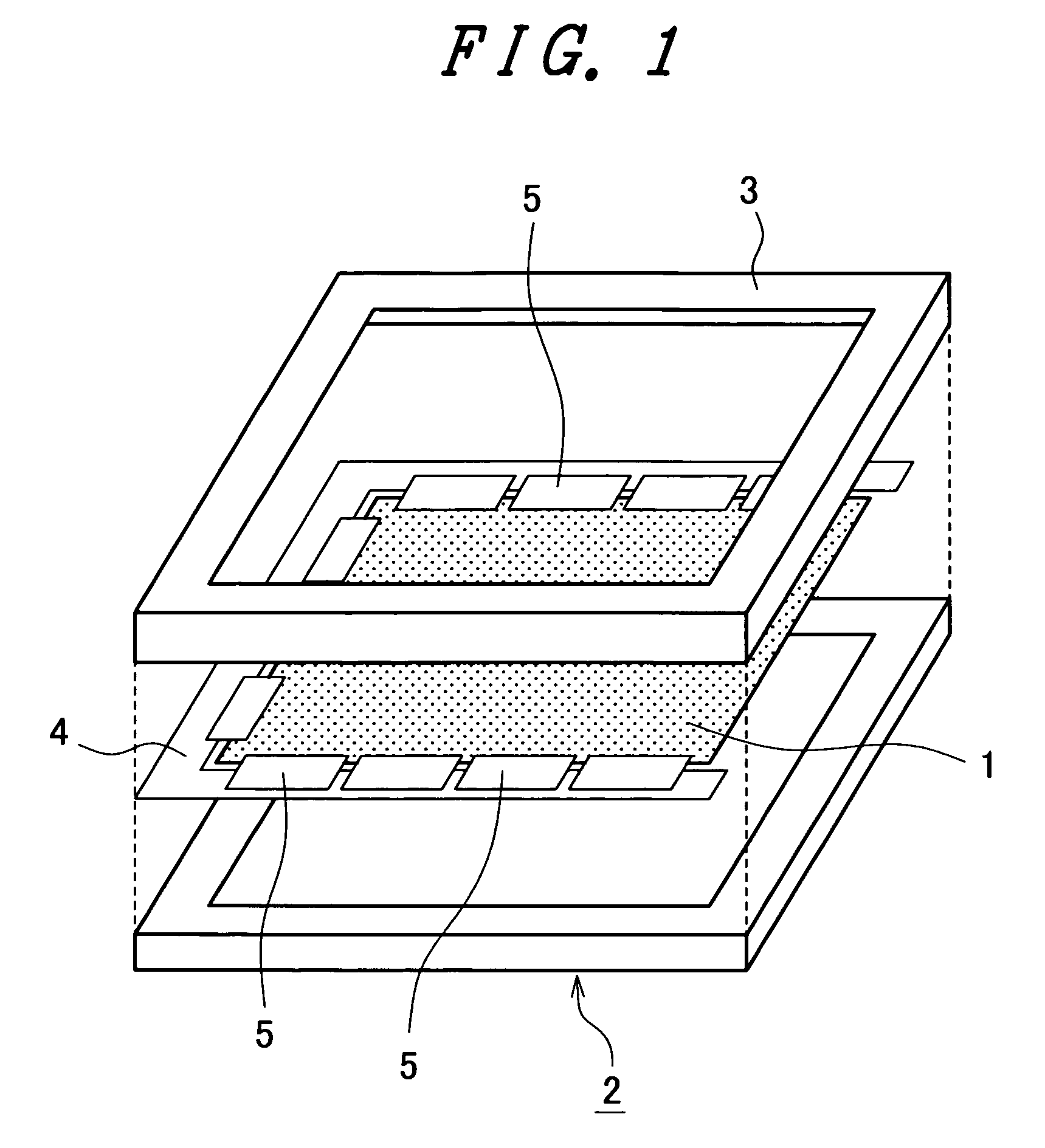
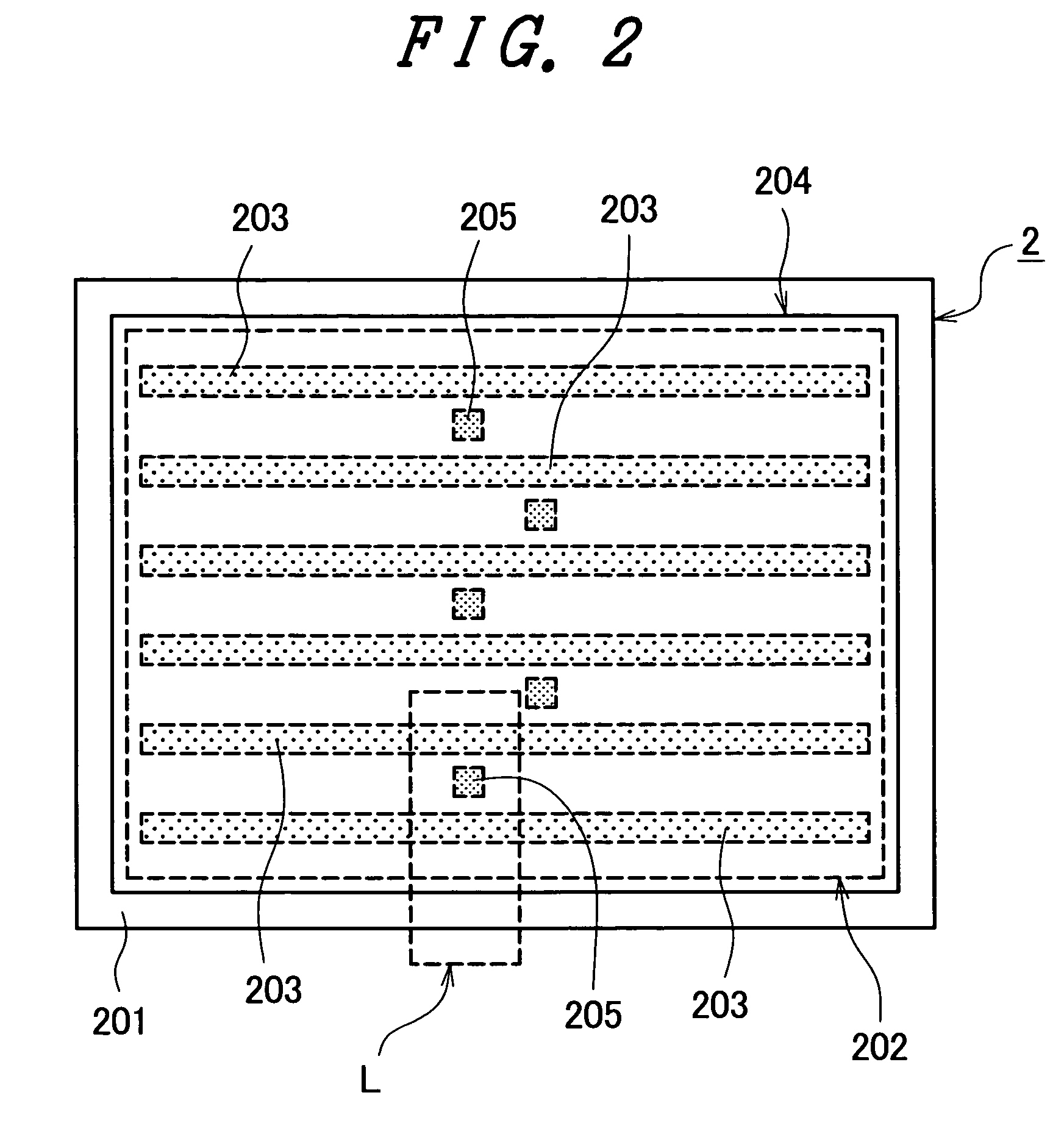
[0052]FIGS. 1 to 5 are schematic diagrams showing the general configuration of a display device of an embodiment according to the present invention. FIG. 1 is a perspective view showing the general configuration of the display device, FIG. 2 is a front v...


PUM

PropertyMeasurementUnit
protruding heightaaaaaaaaaa
timeaaaaaaaaaa

Abstract

A display device includes: a reflection plate; plural light sources disposed above the reflection plate; an optical member disposed above the plural light sources; a support member disposed standing on a bottom surface of the reflection plate; a frame member that houses the reflection plate and the light sources; and a display panel disposed above the optical member. The support member includes: a standing support portion that is disposed standing on and supports the reflection plate; an optical member support portion that supports the optical member; and a leg portion that protrudes downward of the reflection plate and the frame member and is bent in a direction along the standing support member.

Description

[0001]The present application claims priority from Japanese application JP2005-199860 filed on Jul. 8, 2005, the content of which is hereby incorporated by reference into this application.BACKGROUND OF THE INVENTION[0002]1. Field of the Invention[0003]The present invention relates to a display device and a method of assembling the display device, and more particularly to technology effectively applied to a display device which includes support members that are disposed standing on a reflection plate and support an optical member disposed above the reflection plate.[0004]2. Description of the Related Art[0005]Conventionally, among display devices, there is a display device where light sources (a backlight unit) are disposed under (behind) a display panel, such as in a liquid crystal display device, for example.[0006]The backlight unit is one where, for example, light sources such as cold-cathode fluorescent tubes are disposed above (in front of) a reflection plate, and where an optic...

Claims


Application Information

Patent Timeline
Patent Type & Authority Patents(United States)
IPC IPC(8): G02F1/1335
CPCG02F1/133608G02F1/133604G02F1/1335G02F1/1333
Inventor UEDA, SHIRO
Owner JAPAN DISPLAY INC
Why Eureka
Try Eureka