
Method for indicating padding in a digital mobile radio system

a mobile radio and digital technology, applied in the field of digital mobile radio systems, can solve the problems of increasing the amount of time spent using the wireless resource, increasing the length of the packet, and limited the number of bits in the header to be abl

Active Publication Date: 2009-02-10
MOTOROLA SOLUTIONS INC
View PDF13 Cites 4 Cited by
  • Summary
  • Abstract
  • Description
  • Claims
  • Application Information

AI Technical Summary

Benefits of technology

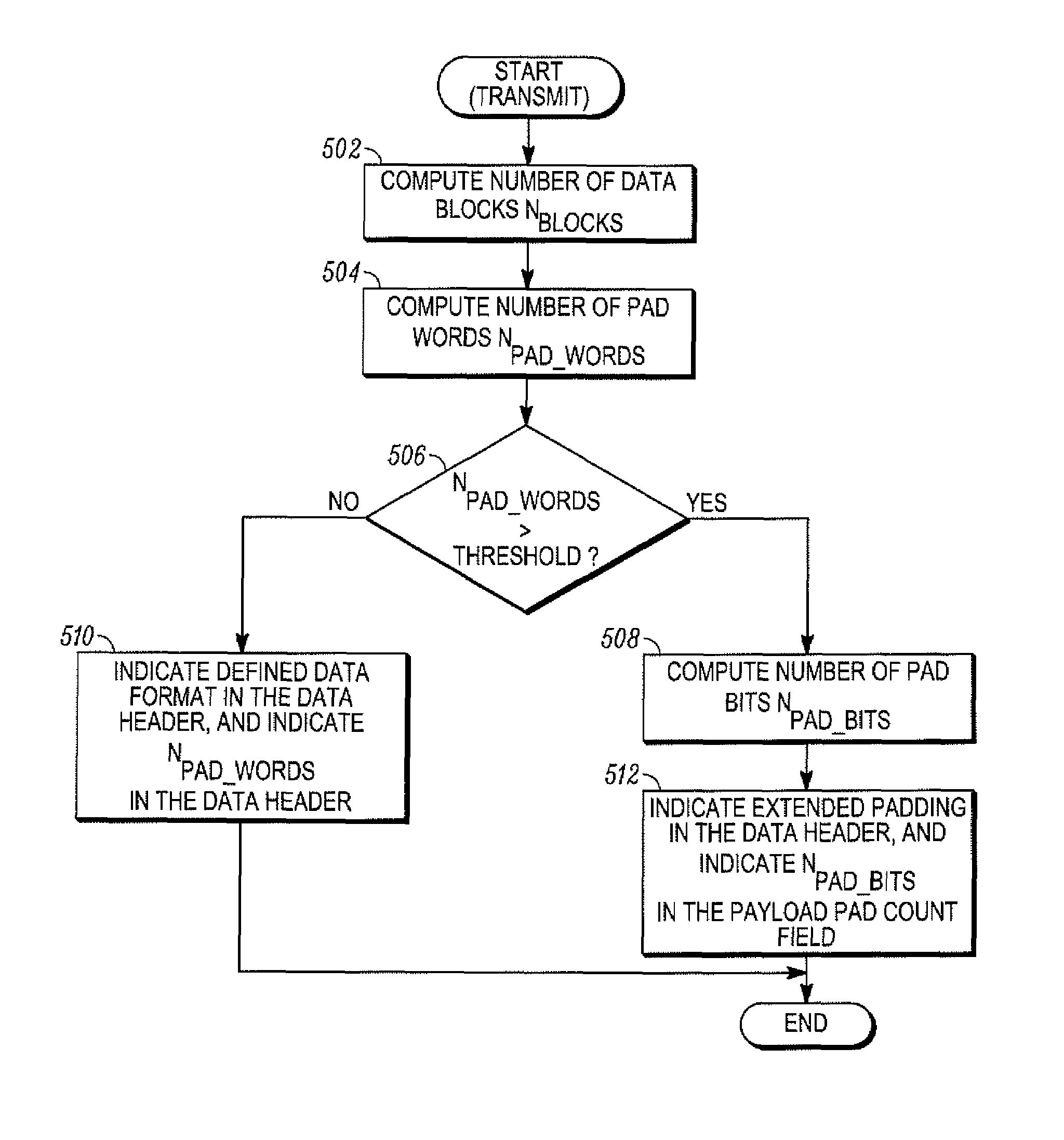
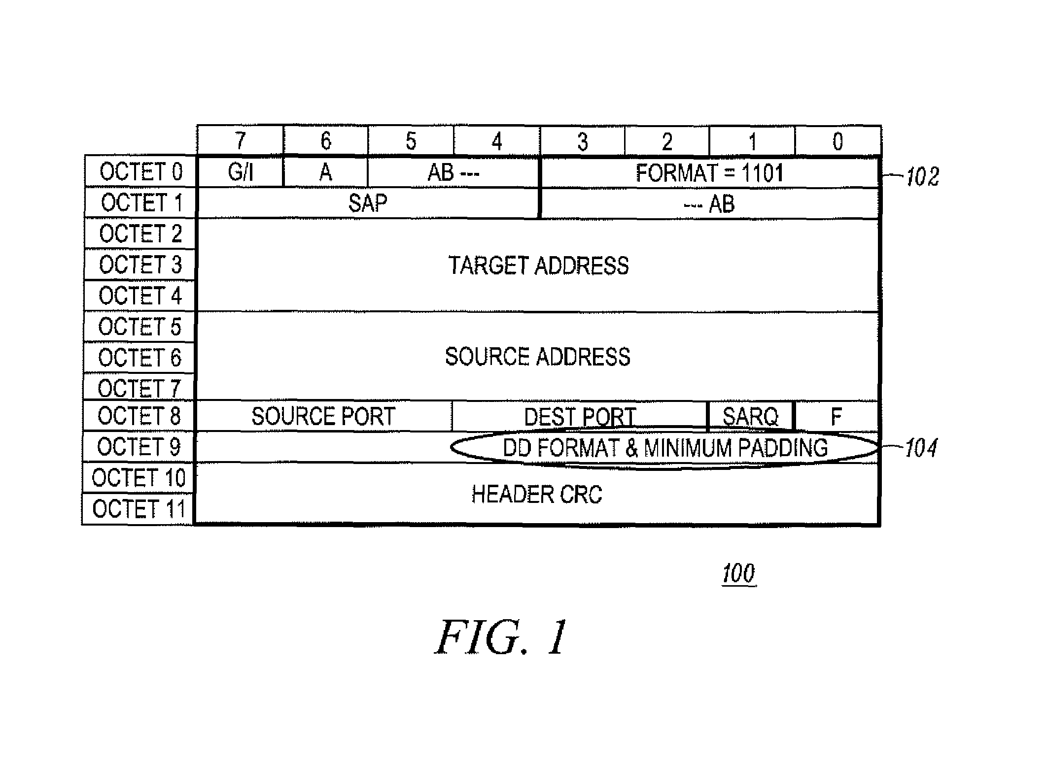
The present invention relates to improving the indication of padding in a digital mobile radio system. The current standard allows for a limited number of bits in the header of a packet to indicate the format of the packet's payload and the required padding. However, increasing the size of the header to accommodate more bits may lead to increased time spent using the wireless resource, decreased system capacity, and increased efficiency in indicating padding. The invention proposes an improved method of indicating padding in a digital mobile radio system by using a short data header that includes a format field and a defined data (DD) format and minimum padding field. The format field defines the type of message, while the DD format field contains the actual data and padding. The invention allows for more efficient indication of padding and reduces the amount of time spent using the wireless resource.

Problems solved by technology

However, there are only a limited number of bits in the header to be able to indicate the format of the packet and to indicate the padding that may be required.
However, increasing the header size increases the length of the packet and, consequently, increases the amount of time spent using the wireless resource.
Further, increasing the amount of time spent using the wireless resource may be an inefficient use of the DMR system and may lead to decreased system capacity.

Method used


Image

  • Method for indicating padding in a digital mobile radio system
  • Method for indicating padding in a digital mobile radio system
  • Method for indicating padding in a digital mobile radio system

Examples


Embodiment Construction

[0014]Before describing in detail embodiments of the present invention, it should be observed that the present invention resides primarily in combinations of method steps and apparatus components. Accordingly, the apparatus components and method steps have been represented where appropriate by conventional symbols in the drawings, showing only those specific details that are pertinent to understanding the present invention so as not to obscure the disclosure with details that will be readily apparent to those of ordinary skill in the art having the benefit of the description herein.

[0015]In this document, relational terms such as first and second, top and bottom, and the like may be used solely to distinguish one entity or action from another entity or action without necessarily requiring or implying any actual such relationship or order between such entities or actions. The terms “comprises,”“comprising,” or any other variation thereof, are intended to cover a non-exclusive inclusi...


PUM


Abstract

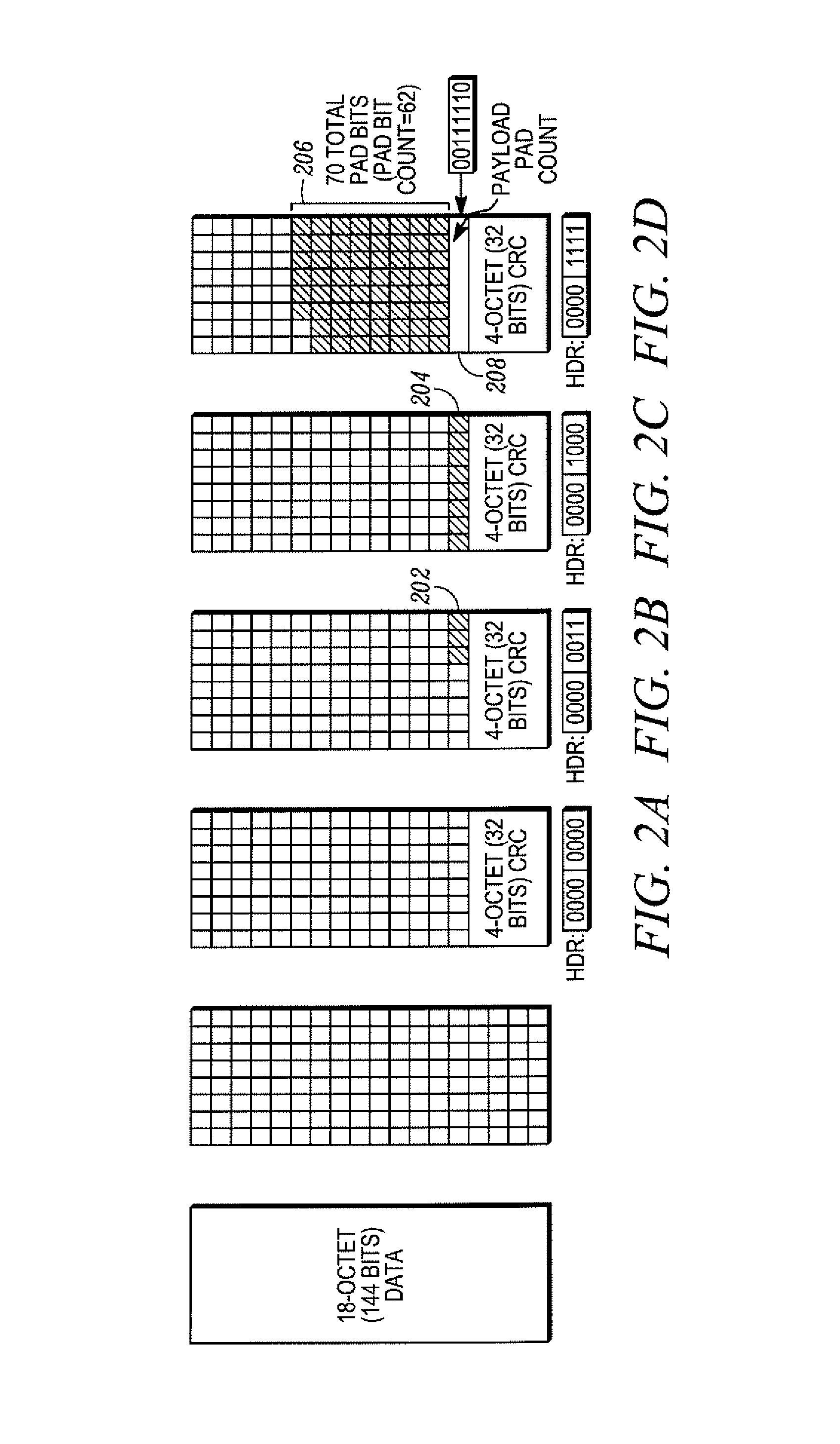
A method for indicating padding in a digital mobile radio is disclosed. The method comprises receiving a packet comprising a header and a defined length blocks portion. The defined length blocks portion comprises payload and a padding portion. The padding portion comprises padding and a payload pad count field. The method further indicates by a pad field in the header to examine the payload pad count field to determine an amount of padding for the padding portion of the defined length blocks portion. The method further indicates an amount of padding for the padding portion in the payload pad count field.

Description

FIELD OF THE INVENTION[0001]The present invention relates generally to digital mobile radio systems and more specifically to the field of indicating padding in a digital mobile radio system.BACKGROUND OF THE INVENTION[0002]The proposed European Telecommunications Standards Institute (ETSI) standard for Digital Mobile Radio (DMR) describes a packet data protocol. In this protocol, each packet comprises a header and defined length blocks portion carrying data (also referred to herein as “payload”). In the proposed ETSI-DMR standard, the header needs to indicate a format of the packet's payload (e.g. 24 bit addresses, 16 bit words, 8 bit words, etc.) and the padding that may be added to the packet to maintain the defined length of the block. However, there are only a limited number of bits in the header to be able to indicate the format of the packet and to indicate the padding that may be required.[0003]One option is to increase the header size so as to accommodate the need to indicat...

Claims


Application Information

Patent Timeline
Patent Type & Authority Patents(United States)
IPC IPC(8): H04J3/24
CPCH04W28/06H04W48/08
Inventor WIATROWSKI, DAVID G.CHOWDHARY, DIPENDRA M.
Owner MOTOROLA SOLUTIONS INC
Learn More