
Control method for high-frequency radio equipment and high-frequency radio system

a radio equipment and control method technology, applied in the field of high-frequency radio equipment systems, can solve the problems of short communication distance, deterioration of transmission quality, code error rate increase, etc., and achieve the effect of improving receiving sensitivity and maintaining transmission quality

Inactive Publication Date: 2009-02-10
NIHON DEMPA KOGYO CO LTD
View PDF23 Cites 2 Cited by
  • Summary
  • Abstract
  • Description
  • Claims
  • Application Information

AI Technical Summary

Benefits of technology

[0026]The present invention was made in view of the above present situation and has an objective to provide a control method for high-frequency radio equipment and a high-frequency radio equipment system in the spread spectrum radio frequency data communication which is interference-tolerant and can maintain transmission quality with improved receiving sensitivity.

Problems solved by technology

That is because, while mutual interference is likely to occur in the frequency band where many communication systems are mixed such as the Industrial Scientific Medical (ISM) band (2.4 GHz band) used for low-power data communication systems including a wireless Local Area Network (LAN) and with a rather high transmission power, the frequency used in many systems is as low as 322 MHz or less in the communication in an extremely low power and its wavelength is long and communication distance is short due to low transmission power, and such a problem hardly occurs.
This prior art, however, performs directive control by weighting a signal received by the adaptive array antenna, and not by adjusting receiving sensitivity by directly selecting a plurality of receiving antennas using a code error rate.
However, the conventional radio equipment systems have a problem that, if there are many equivalent systems in the extreme vicinity in the area or in a radio wave environment where there is more than a little steady interference from other systems, code error rate increases, thereby lowering receiving sensitivity or deteriorating transmission quality.

Method used


Image

  • Control method for high-frequency radio equipment and high-frequency radio system
  • Control method for high-frequency radio equipment and high-frequency radio system
  • Control method for high-frequency radio equipment and high-frequency radio system

Examples


Embodiment Construction

[0046]A preferred embodiment of the present invention will be described referring to the drawings.

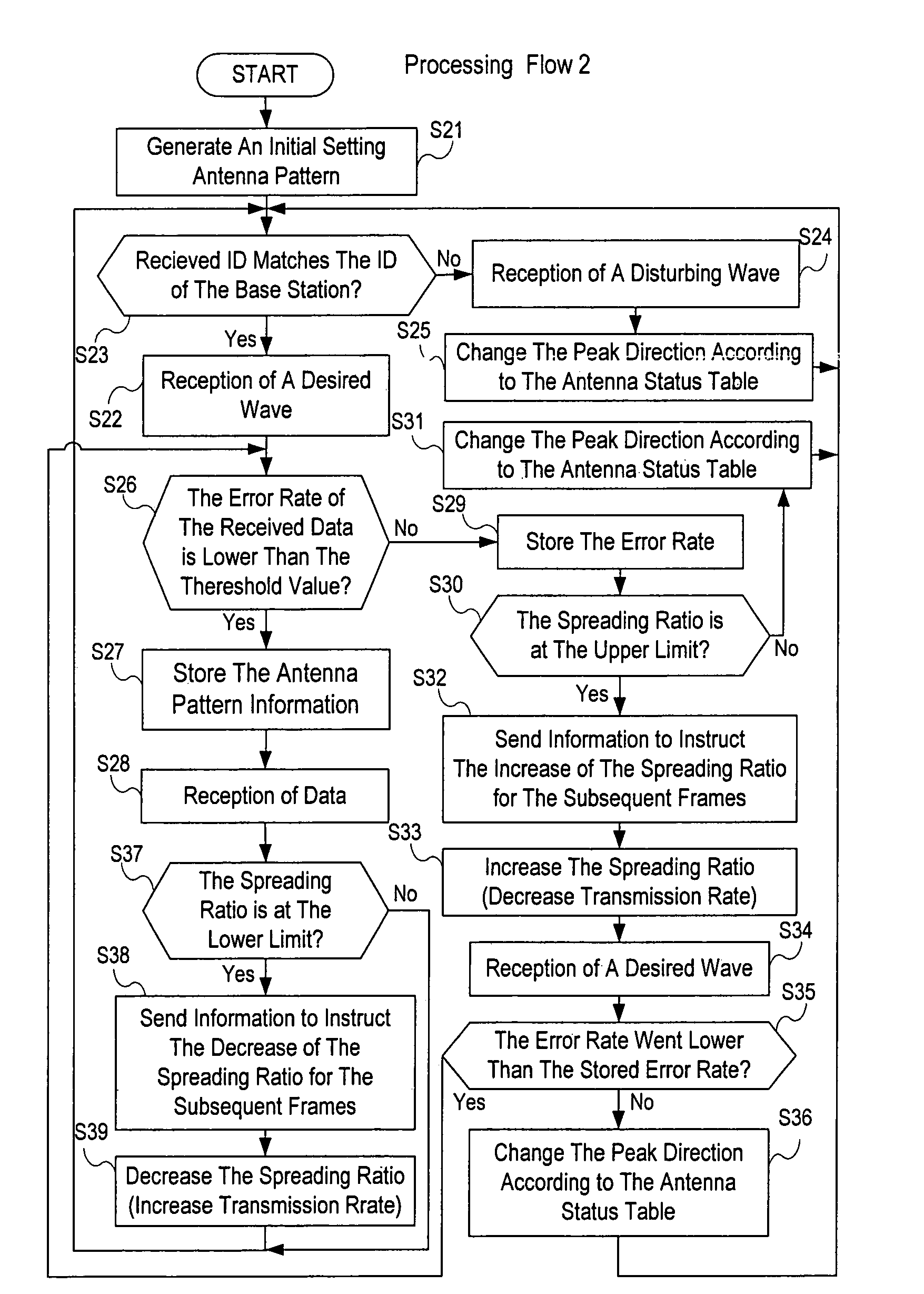
[0047]In a method for controlling high-frequency radio equipment according to the preferred embodiment of the present invention, an extremely weak radio wave signal which was spread spectrum processed and modulated is received and demodulated, despread-spectrum processed received data, taken out, and an antenna pattern specifying a synthesized directivity formed by a plurality of antennas is dynamically changed according to the state of the received data so that a ratio of a desired wave to a disturbing wave is maximized, and a favorable communication with a low error rate can be dynamically realized.

[0048]Also, in the above method for controlling a high-frequency radio equipment, when the communication environment is in the best state, the spreading ratio is decreased (transmission rate is increased) to improve a transmission efficiency, while, when the communication environment is in ...


PUM


Abstract

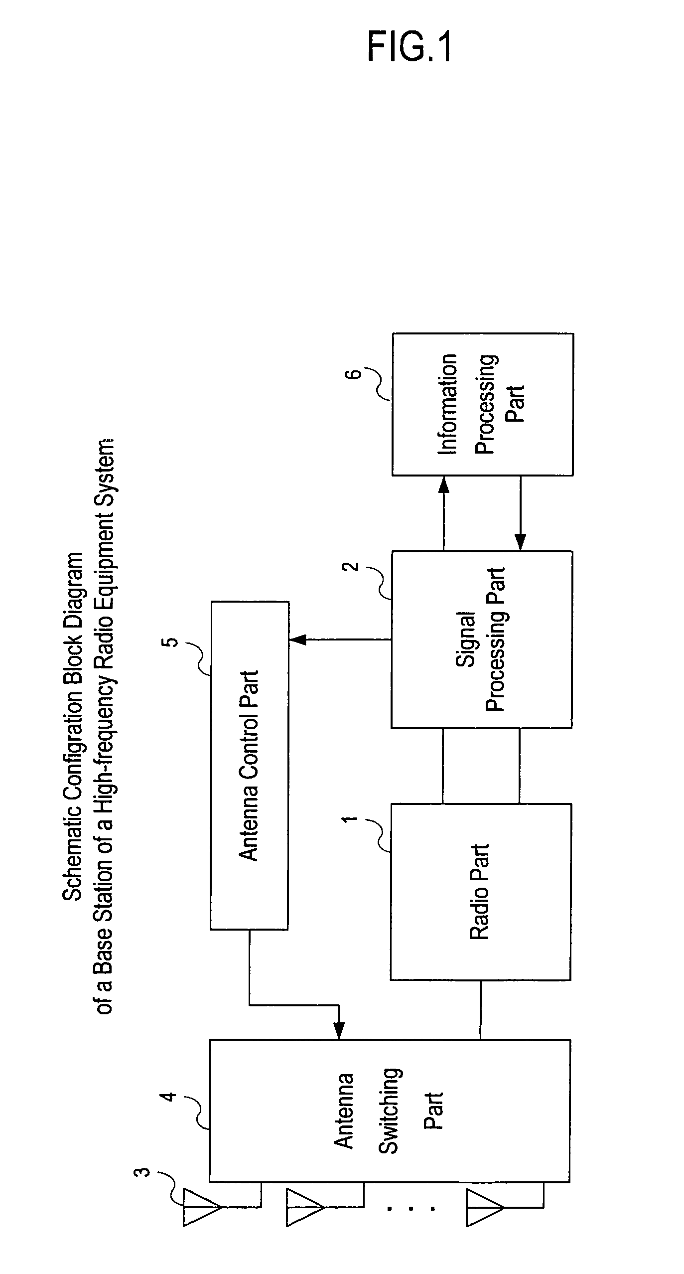
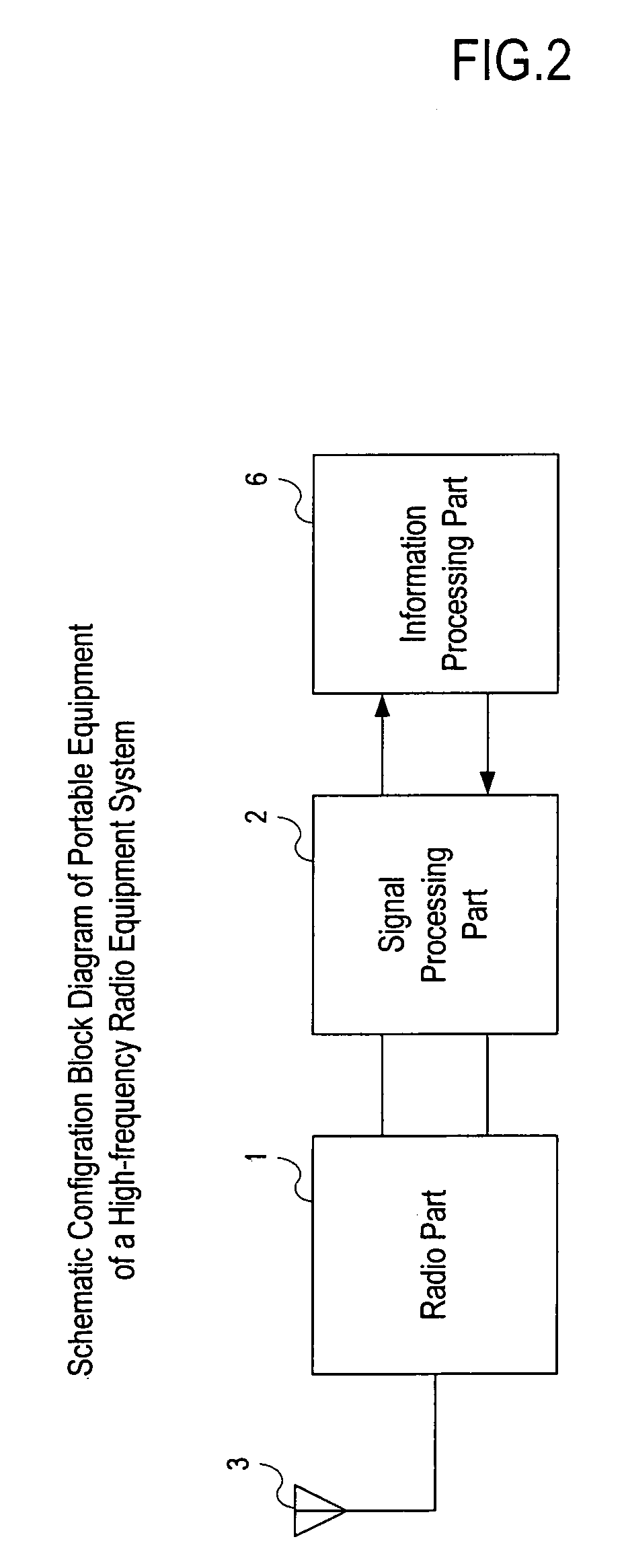
A control method for a high-frequency radio equipment and a high-frequency radio equipment system in spread spectrum radio data communication are provided which are interference-tolerant and can maintain transmission quality with improved receiving sensitivity.A high-frequency radio equipment system provided with, in a base station, an antenna part comprised by a plurality of antennas, a radio part for amplifying a received signal, band-limiting and down-converting it to an intermediate frequency, a signal processing part for carrier-demodulating the signal inputted from the radio part, demodulating the signal which was despread-spectrum processed and synchronized and decoding the received data, an antenna control part for determining a code error rate for the received data inputted from the signal processing part, forming an appropriate antenna pattern based on the error rate and outputting a signal for controlling an antenna switching part according to the information of the antenna pattern.

Description

BACKGROUND OF THE INVENTION[0001]1. Field of the Invention[0002]The present invention relates to a high-frequency radio equipment system suitable for use in the Near Field Communication method and particularly with a control method for a high-frequency radio equipment and a high-frequency radio equipment system which lowers code error rate in a communication environment and realizes favorable communication.[0003]2. Description of the Related Art[0004]The “Near Field Communication method” uses a carrier band signal of an extremely low power which is not regulated by laws and regulations, for example.[0005]As an example of a radio equipment system using the Near Field Communication method, a keyless entry control system is known. This is a system for controlling opening / closing of a vehicle door, start or stop of an engine, etc. to be controlled by radio from a position several to several tens of meters away and it is constituted by a fixed-type base station device mounted on the vehi...

Claims


Application Information

Patent Timeline
Patent Type & Authority Patents(United States)
IPC IPC(8): H04M1/00H04B1/707H04B1/7103H04B7/08H04B7/10
CPCH04B7/0805H04B7/086H04J13/00G07C9/00309G07C2209/61
Inventor ONISHI, NAOKI
Owner NIHON DEMPA KOGYO CO LTD
Learn More