
Wavelength multiplexing apparatus and signal conversion apparatus

a signal conversion and multiplexing technology, applied in multiplex communication, transmission monitoring, instruments, etc., can solve the problems of complex wiring work (including wire binding), not necessarily shared, and difficulty in synchronizing with individual external clock signals. achieve the effect of low cost and maintain transmission quality at a high level

Inactive Publication Date: 2007-06-05
FUJITSU LTD
View PDF6 Cites 0 Cited by
  • Summary
  • Abstract
  • Description
  • Claims
  • Application Information

AI Technical Summary

Benefits of technology

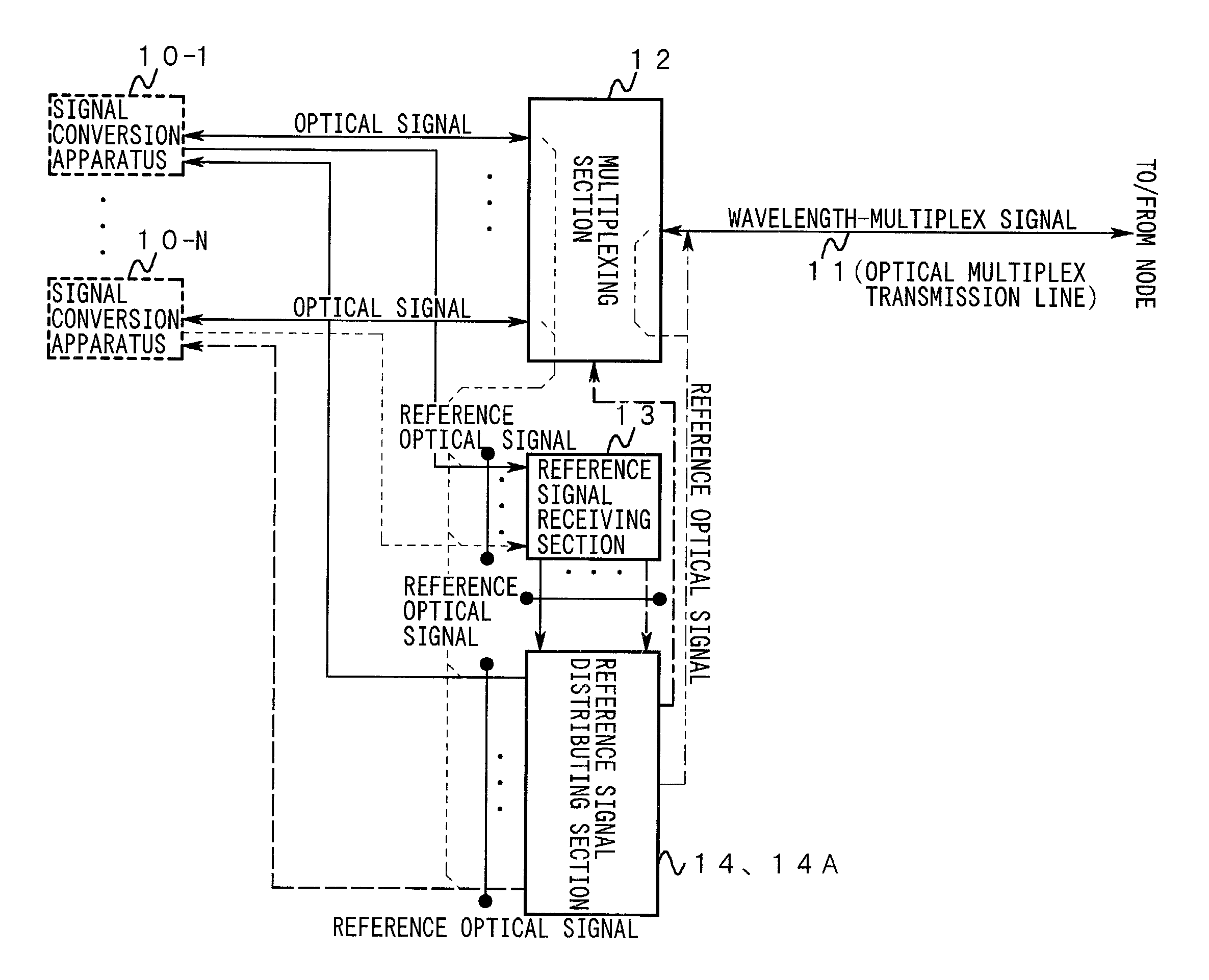
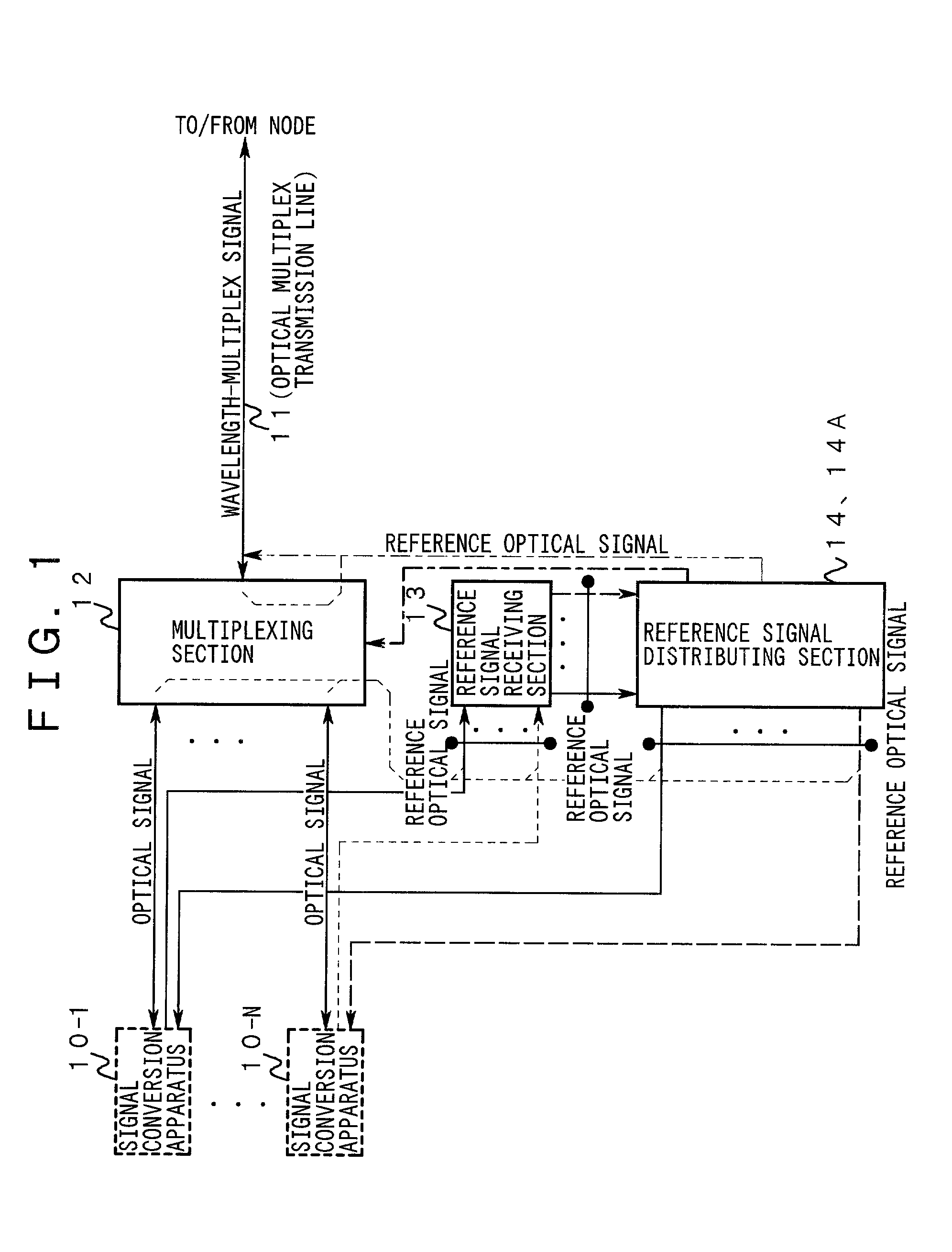
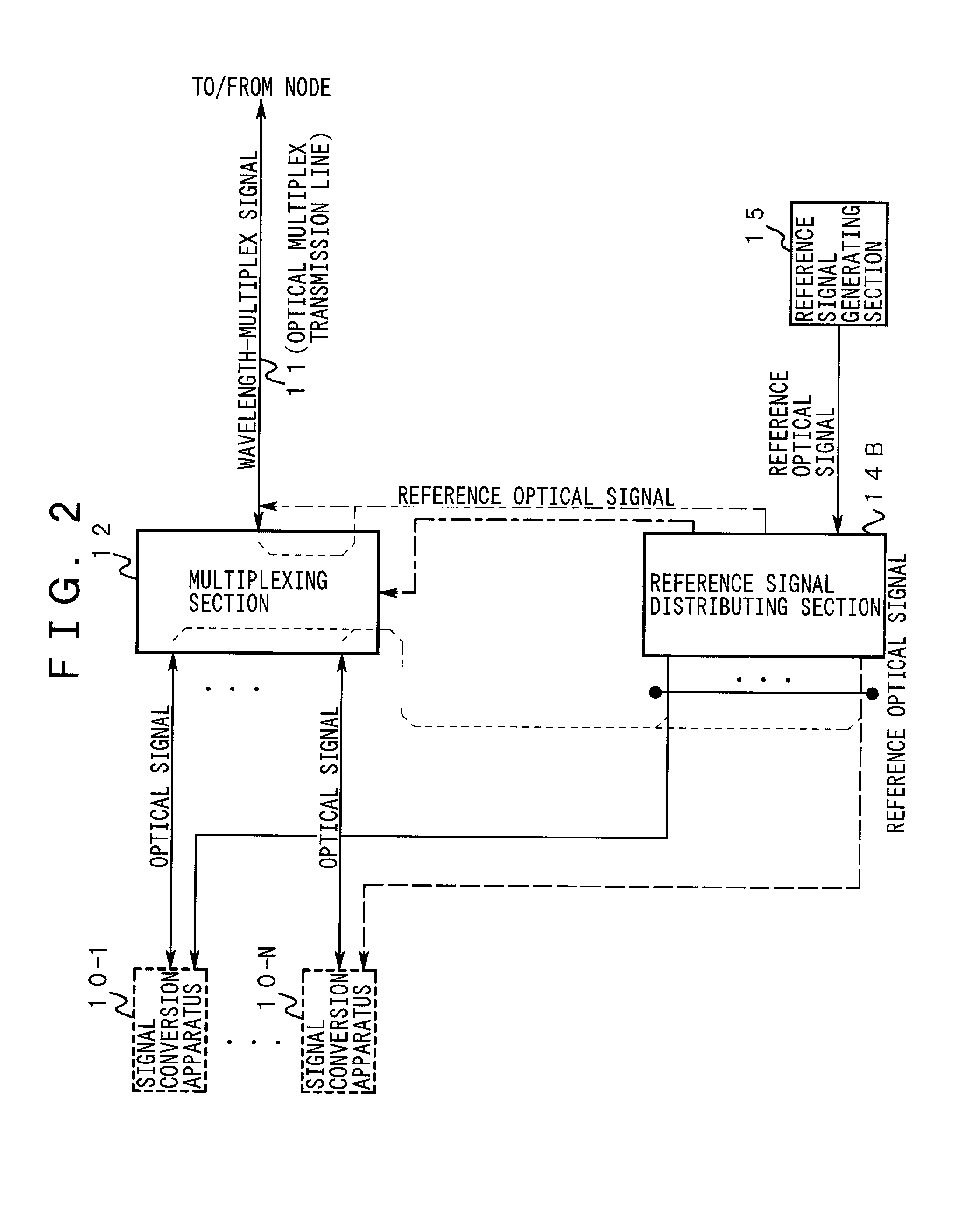
[0057]It is an object of the present invention to provide a wavelength multiplexing apparatus and a signal conversion apparatus which can satisfy, flexibly and at low cost, demands for conditions for office establishment, arrangement of the apparatus in the office premises, and maintenance / operation, and can maintain transmission quality at a high level.
[0058]It is an object of the present invention to simplify and standardize the configuration of optical transmission lines which are necessary for directly delivering a reference optical signal among a plurality of signal conversion apparatuses.

Problems solved by technology

However, since the external clock signal is selected according to the office data and the forms of the maintenance and operation, it is not necessarily shared.
For this reason, it is difficult to realize synchronization with the individual external clock signals which correspond to a combination (group) of the optical transmission lines having a predetermined property in common (for example, an operator such as a telecommunication carrier and a user), due to its cost increases and various limitations caused by construction and the like.
Moreover, complicated wiring work (including wire binding) is necessary in order to underlay the lines for supplying the external clock signal to the OEO converting parts 110-1 to 110-N.
Therefore, the level of the electromagnetic interference (EMI) which is radiated from the communication lines like the above is increased as the number of the communication links increases, and causes the external clock signal to deteriorate its waveform.
Also, there is a possibility that it acts as disturbance on the external apparatus and the transmission system.

Method used


Image

  • Wavelength multiplexing apparatus and signal conversion apparatus
  • Wavelength multiplexing apparatus and signal conversion apparatus
  • Wavelength multiplexing apparatus and signal conversion apparatus

Examples


first embodiment

[0298]FIG. 11 is a diagram showing the present invention.

[0299]This embodiment is characterized in that OEO converting parts 30-1 to 30-N are provided thereto instead of the OEO converting parts 110-1 to 110-N, a wavelength multiplexing part 31 is provided thereto instead of the wavelength multiplexing part 112, and an external clock signal is supplied only to the OEO converting part 30-1.

[0300]The structure of the OEO converting part 30-1 is different from that of the OEO converting part 110-1 in that the following elements are added thereto:[0301]an optical coupler 32-1 one of whose inputs is connected to an output of a wavelength converting part 126u-1 and whose output is connected to a corresponding multiplexing input of the wavelength multiplexing part 31,[0302]an EO converting part 33-1 whose input is connected to an output of a clock selecting part 130-1 and whose output is connected to the other input of the optical coupler 32-1,[0303]an optical filter 34-1 whose input is co...

second embodiment

[0342]FIG. 15 is a diagram showing the present invention.

[0343]The structure of this embodiment is characterized in that an OEO converting part 60-1 is provided instead of the OEO converting part 30-1 and a wavelength multiplexing part 61 is provided instead of the wavelength multiplexing part 31.

[0344]The following are structural differences between the OEO converting part 60-1 and the OEO converting part 30-1.[0345]The optical coupler 32-1 and the EO converting part 33-1 are not provided thereto.[0346]An output of a wavelength converting part 126u-1 is connected to a corresponding input of the wavelength multiplexing part 61.[0347]An optical amplifier 62-1 is provided in the wavelength converting part 126u-1.[0348]An output of a clock selecting part 130-1 is connected to a bias circuit of an LED 63-1 which supplies pumping light to the optical amplifier 62-1.[0349]An optical coupler 34A-1 is provided instead of the optical filter 34-1.[0350]A clock regenerating part 65-1 is provid...

third embodiment

[0368]FIG. 17 is a diagram showing the present invention.

[0369]This embodiment is characterized in that a wavelength multiplexing part 61A is provided instead of the wavelength multiplexing part 61.

[0370]The structure of the wavelength multiplexing part 61A is different from that of the wavelength multiplexing part 61 as follows:[0371]A selecting part 66 whose inputs are connected to clock terminals of all or a part of clock extracting parts 64-1 to 64-N (supposing that the inputs are connected to all of them for simplifying the explanation) is provided thereto.[0372]An output of the selecting part 66, instead of the clock output of the clock extracting part 64-1, is connected to a bias circuit of an LED 67.

[0373]Hereinafter, the operation of this embodiment will be explained.

[0374]In this embodiment, not only an OEO converting part 60-1, but also OEO converting parts 60-2 to 60-3 respectively supply an upstream optical signal in parallel, whose intensity is modulated according to t...


PUM


Abstract

The present invention relates to a wavelength multiplexing apparatus for multiplexing and / or demultiplexing a plurality of optical signals in the wavelength region and a signal conversion apparatus for interfacing a transmission line corresponding to any of the optical signals with the wavelength multiplexing apparatus. By using these apparatus according to the invention, the signal to be a reference for synchronization between the wavelength multiplexing apparatus and the signal conversion apparatus is reliably delivered via an existing optical transmission line therebetween, without the reduction of transmission quality and the limitation on modulation systems. Therefore, in an optical transmission system with the present invention applied thereto, it is possible to meet conditions for office establishment and arrangement of the apparatus and satisfy the demands for maintenance / operation flexibly and at a low cost. Further, service quality and reliability are maintained at high levels.

Description

BACKGROUND OF THE INVENTION[0001]1. Field of the Invention[0002]The present invention relates to a wavelength multiplexing apparatus for multiplexing and / or demultiplexing a plurality of optical signals in the wavelength region and a signal conversion apparatus for interfacing a transmission line which corresponds to any of these optical signals with the wavelength multiplexing apparatus.[0003]2. Description of the Related Art[0004]Recently, technology for realizing optical devices such as a light source with stable wavelength and level, an optical combiner with narrow band has been progressed significantly. For this reason, wavelength division multiplexing (WDM) has been actively applied to the trunk line system and the access network.[0005]FIG. 34 is a diagram showing a first structural example of a node adapted to the wavelength division multiplexing.[0006]In the drawing, a common external clock signal is supplied to OEO converting parts 110-1 to 110-N. Up links of full-duplex op...

Claims


Application Information

Patent Timeline
Patent Type & Authority Patents(United States)
IPC IPC(8): H04B10/00H04B10/06H04J14/02H04J14/00G02B6/43H04B10/54H04B17/00H04J3/06
CPCH04J3/0685H04J14/02G02B6/43
Inventor ONO, TAKESHIKUNIMATSU, KAZUHIROEGOSHI, HIROYASOGA, TADASHI
Owner FUJITSU LTD
Learn More