Multicarrier communication apparatus, integrated circuit, and multicarrier communication method

a communication apparatus and multi-carrier technology, applied in the direction of payload allocation, digital transmission, transmission path sub-channel allocation, etc., can solve the problem of not maximizing the transmission rate corresponding to the transmission status, and achieve the effect of increasing transmission rate, maintaining transmission quality, and increasing transmission ra

Inactive Publication Date: 2010-11-30
PANASONIC CORP
View PDF11 Cites 2 Cited by
  • Summary
  • Abstract
  • Description
  • Claims
  • Application Information

AI Technical Summary

Benefits of technology

[0008]According to this configuration, the modulation methods of subcarriers are determined according to the statistics of the calculated noise levels of the plurality of subcarriers. Therefore, it is possible to increase transmission rate, while maintaining transmission quality, according to transmission status.
[0010]According to this configuration, the modulation methods of subcarriers are determined according to the statistics of the calculated noise levels of the plurality of subcarriers. Therefore, it is possible to increase transmission rate, while maintaining transmission quality, according to transmission status.
[0012]According to this method, the modulation methods of subcarriers are determined according to the statistics of the calculated noise levels of the plurality of subcarriers. Therefore, it is possible to increase transmission rate, while maintaining transmission quality, according to transmission status.
[0013]The present invention provides a multicarrier communication apparatus, an integrated circuit, and a multicarrier communication method, which perform an adaptive modulation for each subcarrier and are capable of increasing transmission rate while maintaining transmission quality.

Problems solved by technology

However, in the above-described conventional communication method, since fixed thresholds are used to determine a primary modulation method for each subcarrier, when considering the multicarrier communication in whole, there is a problem that the transmission rate corresponding to a transmission status is not maximized.

Method used


Image

  • Multicarrier communication apparatus, integrated circuit, and multicarrier communication method
  • Multicarrier communication apparatus, integrated circuit, and multicarrier communication method
  • Multicarrier communication apparatus, integrated circuit, and multicarrier communication method

Examples


Embodiment Construction

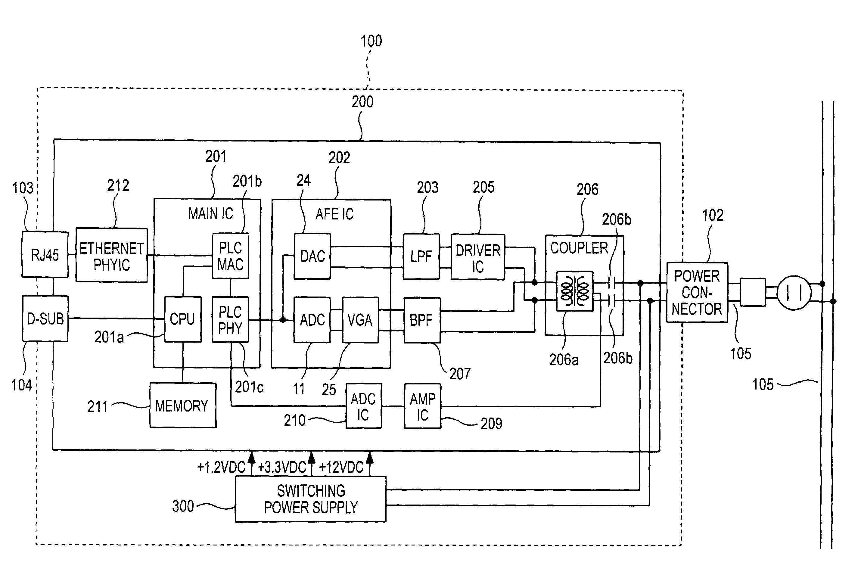
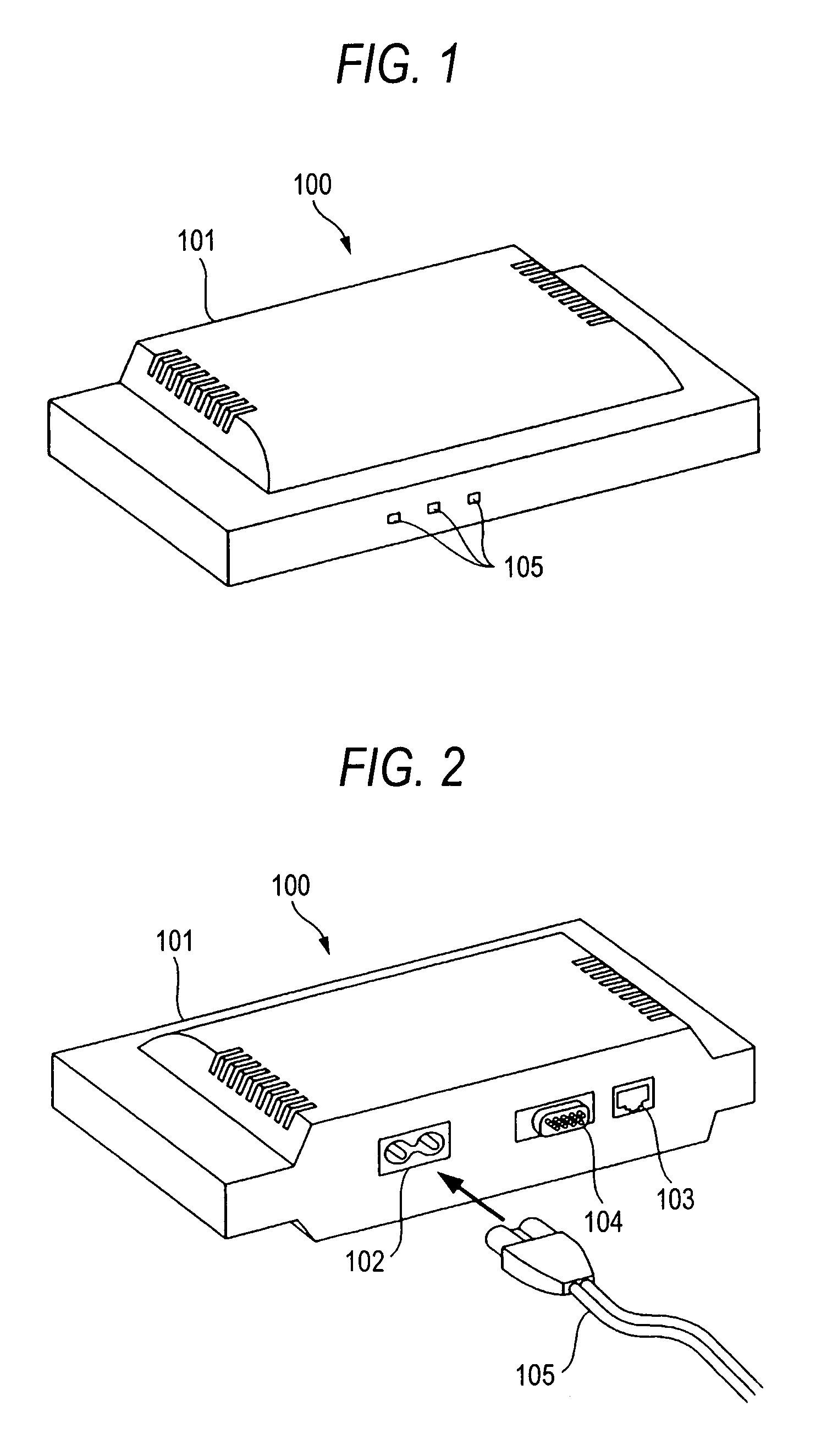
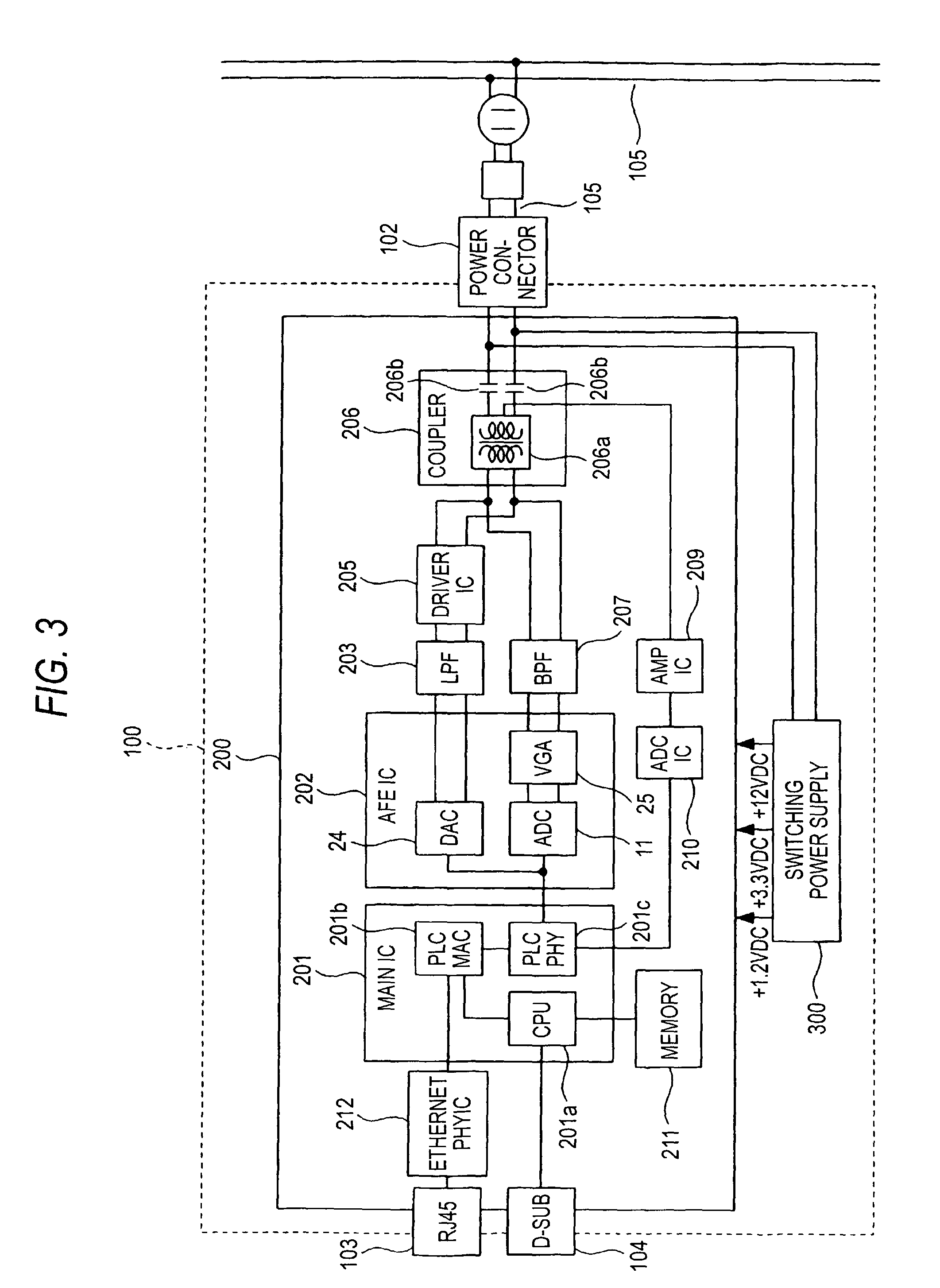
[0026]FIG. 1 is an exterior perspective view showing a front side of a multicarrier communication apparatus according to an embodiment. FIG. 2 is an exterior perspective view showing a back side of the multicarrier communication apparatus according to the embodiment. Multicarrier communication apparatus 100 according to the embodiment is a modem, as shown in FIGS. 1 and 2. Multicarrier communication apparatus 100 has chassis 101. On the front of chassis 101, as shown in FIG. 1, display 105 having LEDs (Light Emitting Diodes) and the like is provided. On the back of chassis 101, as shown in FIG. 2, power connector 102, modular jack 103 such as a RJ45 or the like for LAN (Local Area Network) connection, and Dsub connector 104 are provided. As shown in FIG. 2, power line 105, such as a parallel cable, is connected to power connector 102. A LAN cable, which is not shown in the figure, is connected to modular jack 103. A Dsub cable, which is not shown in the figure, is connected to Dsub ...


PUM


Abstract

Channel estimation unit 16 includes CNR calculation unit 17, threshold setting unit 18, and modulation method determination unit 19. CNR calculation unit 17 calculates a CNR for each of a plurality of subcarriers from a received multicarrier communication signal. Threshold setting unit 18 takes statistics of a plurality of calculated CNRs, and, based on the statistics, sets CNR thresholds each assigned to one of a plurality of modulation methods. Modulation method determination unit 19 uses the set thresholds to determine a modulation method for each subcarrier, according to the calculated CNR of the subcarrier.

Description

TECHNICAL FIELD[0001]The present invention relates to a multicarrier communication apparatus, an integrated circuit, and a multicarrier communication method, in which communication is performed via a transmission line, through which a multicarrier communication signal is transmitted.BACKGROUND ART[0002]Conventionally, for a multicarrier communication in which a plurality of subcarriers are used for transmitting data in parallel, there has been a communication method in which a primary modulation method (in other words, “modulation scheme”) is selected for each subcarrier according to a preconfigured transmission status.[0003]In this communication method, a plurality of adaptive modulation blocks are provided for each subcarrier. A transmission status of each adaptive modulation block is divided into a plurality of levels (for example, 4 levels) according to a set of thresholds. For each level of the transmission status, an optimal primary modulation method is selected for transmissi...

Claims


Application Information

Patent Timeline
Patent Type & Authority Patents(United States)
IPC IPC(8): H04K1/10
CPCH04L27/2608H04L5/0044
Inventor KOGA, HISAOKODAMA, NOBUTAKA
Owner PANASONIC CORP
Why Eureka
Try Eureka