Vehicle control apparatus and method

a technology of vehicle control and control apparatus, which is applied in the direction of electrical control, fluid couplings, gearing, etc., can solve the problems of increasing the possibility of engine stall, reducing the brake force of the engine, and limited coast-downshift, so as to improve fuel economy and improve vehicle driveability

Inactive Publication Date: 2009-02-17
TOYOTA JIDOSHA KK
View PDF8 Cites 8 Cited by
  • Summary
  • Abstract
  • Description
  • Claims
  • Application Information

AI Technical Summary

Benefits of technology

[0020]The invention provides a vehicle control apparatus and a vehicle control method for a vehicle having an engine with a feel injection valve and an automatic transmission with a torque converter having a lock-up clutch. The vehicle control apparatus and the vehicle control method of the invention improve the fuel economy and provide a good vehicle driveability by ensuring modest engine deceleration of the vehicle.
[0024]As such, the above-described vehicle control apparatus ensures modest deceleration of the vehicle while extending the fuel-cut duration, causing none of a situation where the engine brake becomes too weak and thus the driver needs to brake the vehicle manually and a situation where the vehicle nose-dives due to too strong engine brake.
[0026]Accordingly, the invention improves the fuel economy by extending the fuel-cut duration and provides a good vehicle driveability by ensuring modest deceleration of the vehicle during deceleration of the vehicle.

Problems solved by technology

If the lock-up clutch of the torque converter is in the released state when the vehicle is decelerating as described above, it causes a loss of torque (rotational force) transferred from the output side to the input side of the torque converter, resulting in a decrease in the engine brake force.
However, if the threshold is lowered excessively, it increases the possibility of engine stall and therefore it is not desirable.
That is, the coast-downshift is limited when the fuel-cut and the slip control are being executed.
For example, when the vehicle is traveling on a downhill road, not a flat road, the larger the downhill gradient of the downhill road, the smaller the deceleration of the vehicle becomes, and even in this case, after the automatic transmission has been downshifted to the coast-downshift lower limit transmission speed during the coast-downshift control, the fuel-cut and the slip control of the lock-up clutch are discontinued and the fuel supply resumes, which eliminates the feeling of deceleration and reduces the fuel improving effect.

Method used


Image

  • Vehicle control apparatus and method
  • Vehicle control apparatus and method
  • Vehicle control apparatus and method

Examples


Embodiment Construction

[0036]Hereinafter, an example embodiment of the invention will be described with reference to FIG. 1 to FIG. 8.

[0037]Prior to describing a vehicle control apparatus of the example embodiment, a vehicle power train incorporating the vehicle control apparatus will be described.

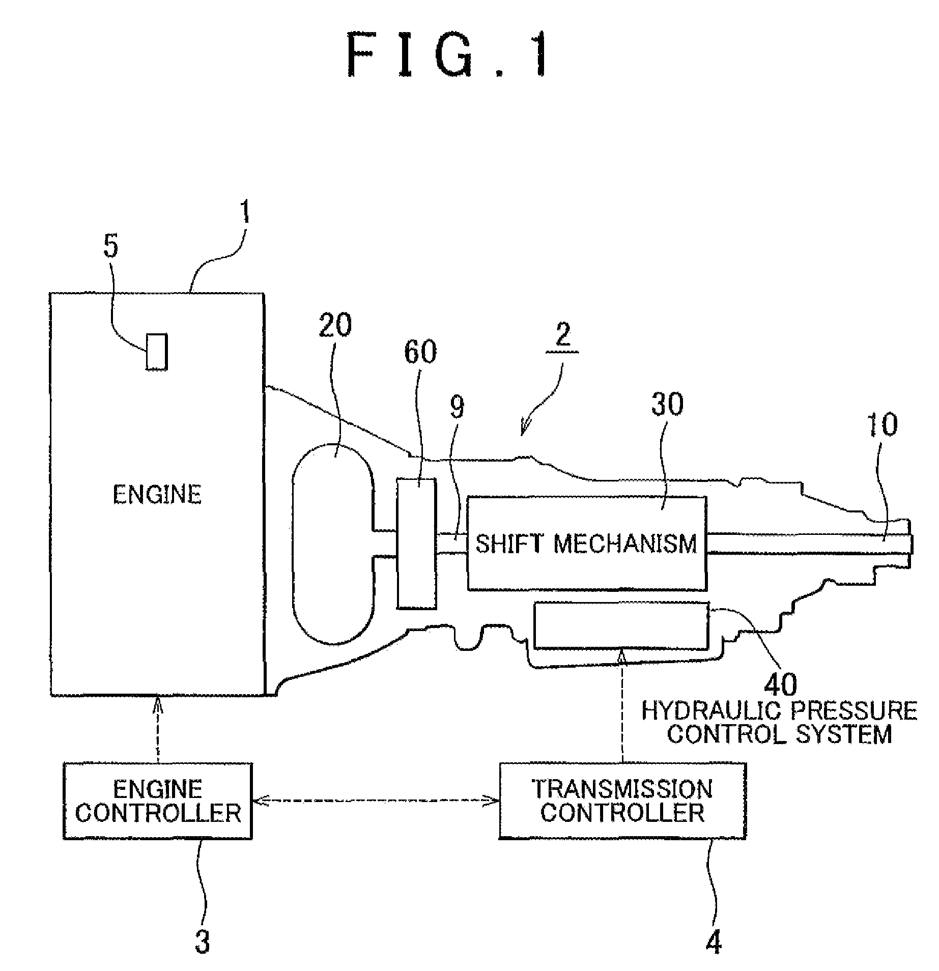
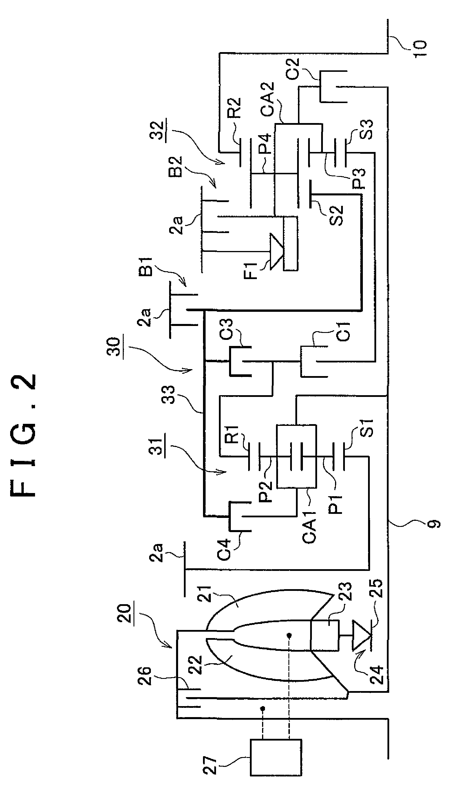
[0038]FIG. 1 is a view schematically showing the configuration of the vehicle power train incorporating the vehicle control apparatus of the example embodiment. FIG. 2 is a skeleton view illustrating an example structure of the automatic transmission shown FIG. 1. FIG. 3 is a perspective view schematically showing the structure of the shift mechanism shown in FIG. 1 and FIG. 2.

[0039]Referring, to FIG. 1, the power train is constituted of an engine 1, an automatic transmission 2, an engine controller 3, and a transmission controller 4.

[0040]The engine 1 produces rotational force by combusting air-fuel mixtures obtained by mixing the air drawn front the outside and the fuel injected from fuel injectors 5 at a give...


PUM


Abstract

A vehicle control apparatus includes a first fuel-cut duration extending portion that, when a fuel-cut is being executed during deceleration of the vehicle, slows the decrease in the engine speed by executing a slip control of a lock-up clutch; and a second fuel-cut duration extending portion which, when the engine speed has decreased to a coast-downshift threshold, which is higher by a given amount than a fuel-cut cancellation threshold, while the slip control is being executed, allows to downshift the automatic transmission if the road on which the vehicle is presently traveling has a downhill gradient that is larger than a reference value.

Description

INCORPORATION BY REFERENCE[0001]The disclosure of Japanese Patent Application No. 2007-004147 filed on Jan. 12, 2007 including the specification, drawings and abstract is incorporated herein by reference in its entirety.BACKGROUND OF THE INVENTION[0002]1. Field of the Invention[0003]The invention relates to a vehicle control apparatus and a vehicle control method for a vehicle having an engine with a fuel injection valve and an automatic transmission with a torque converter having a lock-up clutch.[0004]2. Description of the Related Art[0005]Recently, toque converters provided in automatic transmissions are often provided with a lock-up clutch via which the input side (pump impeller side) and the output side (turbine runner side) of the torque converter are directly coupled with each other when needed.[0006]More specifically, when the lock-up clutch is applied, the input side (pump impeller side) and the output side (turbine runner side) of the toque converter are directly coupled w...

Claims


Application Information

Patent Timeline
Patent Type & Authority Patents(United States)
IPC IPC(8): F02D41/12B60W10/04B60W10/10F02D29/00F16H59/66F16H59/74F16H61/14F16H61/16F16H61/68F16H61/684F16H61/686F16H63/40F16H63/50
CPCB60W30/18136F02D41/021F02D41/123B60W10/10B60W10/196Y10T477/677F02D2200/702Y10S477/901Y10T477/675
Inventor KIMURA, SHIGERUSATOU, TOSHIMITSU
Owner TOYOTA JIDOSHA KK
Why Eureka
Try Eureka