Anchoring device for pipe coupling

a technology of clamping device and pipe coupling, which is applied in the direction of fluid pressure sealing joints, non-disconnectible pipe joints, joints with sealing surfaces, etc., can solve the problems of disproportionate bulkyness of known clamping devices in relation to pipework they connect, and the conversion of non-restrained pipe joints to non-restricted

Inactive Publication Date: 2009-02-17
TAYLOR KERR COUPLINGS
View PDF19 Cites 21 Cited by
  • Summary
  • Abstract
  • Description
  • Claims
  • Application Information

AI Technical Summary

Problems solved by technology

Attempts to envelope the existing coupling by an external gripping means have been expensive, clumsy, bulky and heavy and aesthetically unpleasing which is unacceptable in applications such as drainage pipes for buildings where the pipework is often visible.
Thus, in many cases, the known clamping device can b

Method used


Image

  • Anchoring device for pipe coupling
  • Anchoring device for pipe coupling
  • Anchoring device for pipe coupling

Examples


Embodiment Construction

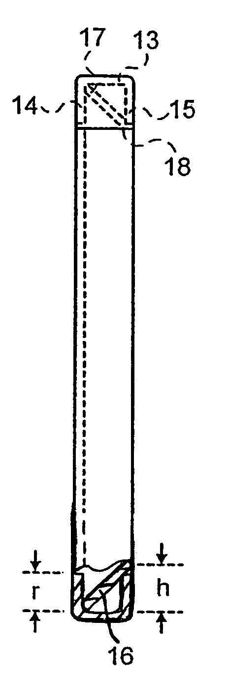
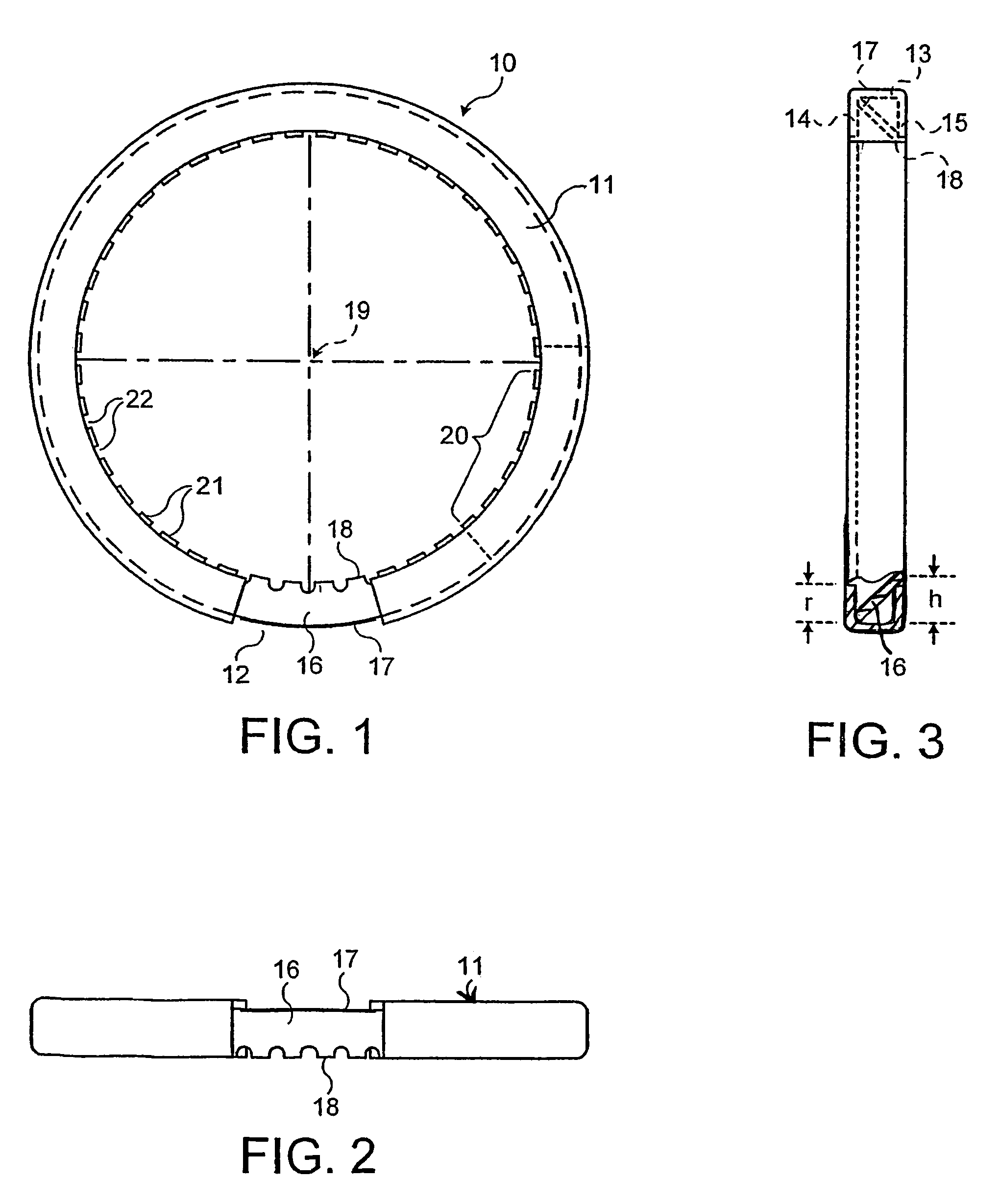
[0018]Referring to FIG. 1, an anchoring device 10 comprises an annular channel 11 formed as an incomplete ring with a circumferential gap 12. The channel has a web portion 13 with flanges 14 and 15 projecting radially inwardly from the axial ends of the web portion. The channel 11 is formed from sheet steel.

[0019]An annular gripping ring 16 is of frusto-conical form with an outer edge 17 and an inner edge 18. The ring 16 subtends an angle of greater than 360° at the axis 19 of the device so as to overlap in the region 20. The inner edge of the gripping ring 16 is formed with teeth 21 which are separated from one another by gaps 22. The inner edges of the teeth are machined to provide sharp edges which can bite into the outer surface of a pipe. The teeth are not bent but flat so as to lie in the conical plane of the gripping ring so that they can pass smoothly over one another as the ring is compressed. The annular gripping ring is of steel.

[0020]As can be seen particularly in FIG. 3...


PUM


Abstract

An anchoring device for a pipe coupling including an annular channel of generally U-shaped cross-section. The channel has a web portion with flanges and projecting radially inwardly. A frusto-conical gripping ring is located in the channel with its outer edge inside the web portion adjacent one of the flanges and its inner edge adjacent the other flange and projecting inwardly beyond this latter flange. The annular channel forms an incomplete ring and is compressible circumferentially. The anchoring device is fitted inside a clamping device, which fits around a pipe coupling. The clamping device has a tensioning for tightening the clamping device around the pipe, compressing the annular channel and causing the inner edge of the frusto-conical gripping ring to engage the outer surface of the pipe and thus grip the pipe.

Description

FIELD OF THE INVENTION[0001]The present invention relates to pipe couplings and is concerned with a system for anchoring pipes to lock them axially together. It has particular application where it is necessary to adapt existing pipe joining methods, such as clamps, collars or bell ends, to accommodate means for axially restraining them.BACKGROUND OF THE INVENTION[0002]Some known pipe couplings have been designed which have no provision for axial restraint. Changes in circumstances may require such couplings to perform to a higher specification than that of the original design. This leads to a requirement for axial locking of the pipes to be added to the coupling. Attempts to envelope the existing coupling by an external gripping means have been expensive, clumsy, bulky and heavy and aesthetically unpleasing which is unacceptable in applications such as drainage pipes for buildings where the pipework is often visible.[0003]There is a need for a self-contained anchoring device which c...

Claims


Application Information

Patent Timeline
IPC IPC(8): F16L17/00F16L21/02F16L21/06
CPCF16L21/065F16L21/08
Inventor WEBB, IAN RICHARDTAYLOR, NEIL JOHN
Owner TAYLOR KERR COUPLINGS
Why Eureka
Try Eureka