
Method for processing acoustic reflections in array data to image near-borehole geological structure

a signal and array data technology, applied in the field of signal data collection and processing, can solve the problems of limited depth that these devices can monitor within the formation, skewed data, and difficulty in downhole imaging, so as to enhance the moveout difference, and reduce the distance between the signal transmitter and the receiver

Active Publication Date: 2009-02-17
BAKER HUGHES INC
View PDF14 Cites 20 Cited by
  • Summary
  • Abstract
  • Description
  • Claims
  • Application Information

AI Technical Summary

Benefits of technology

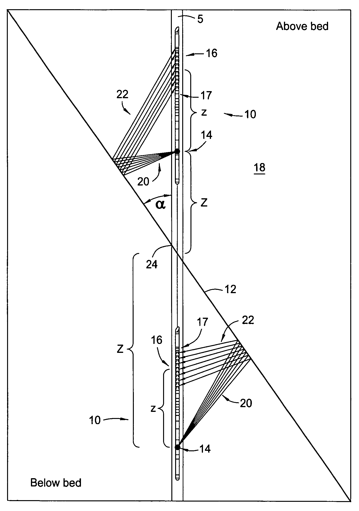
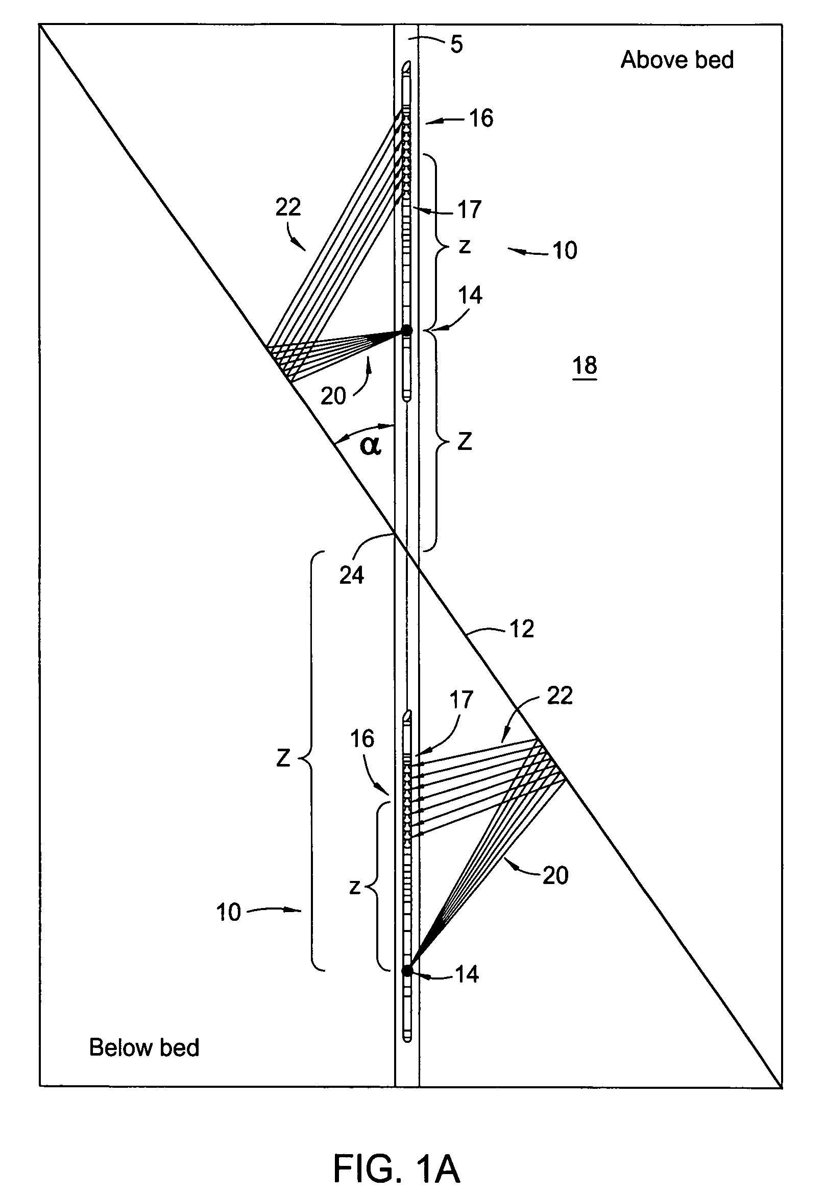
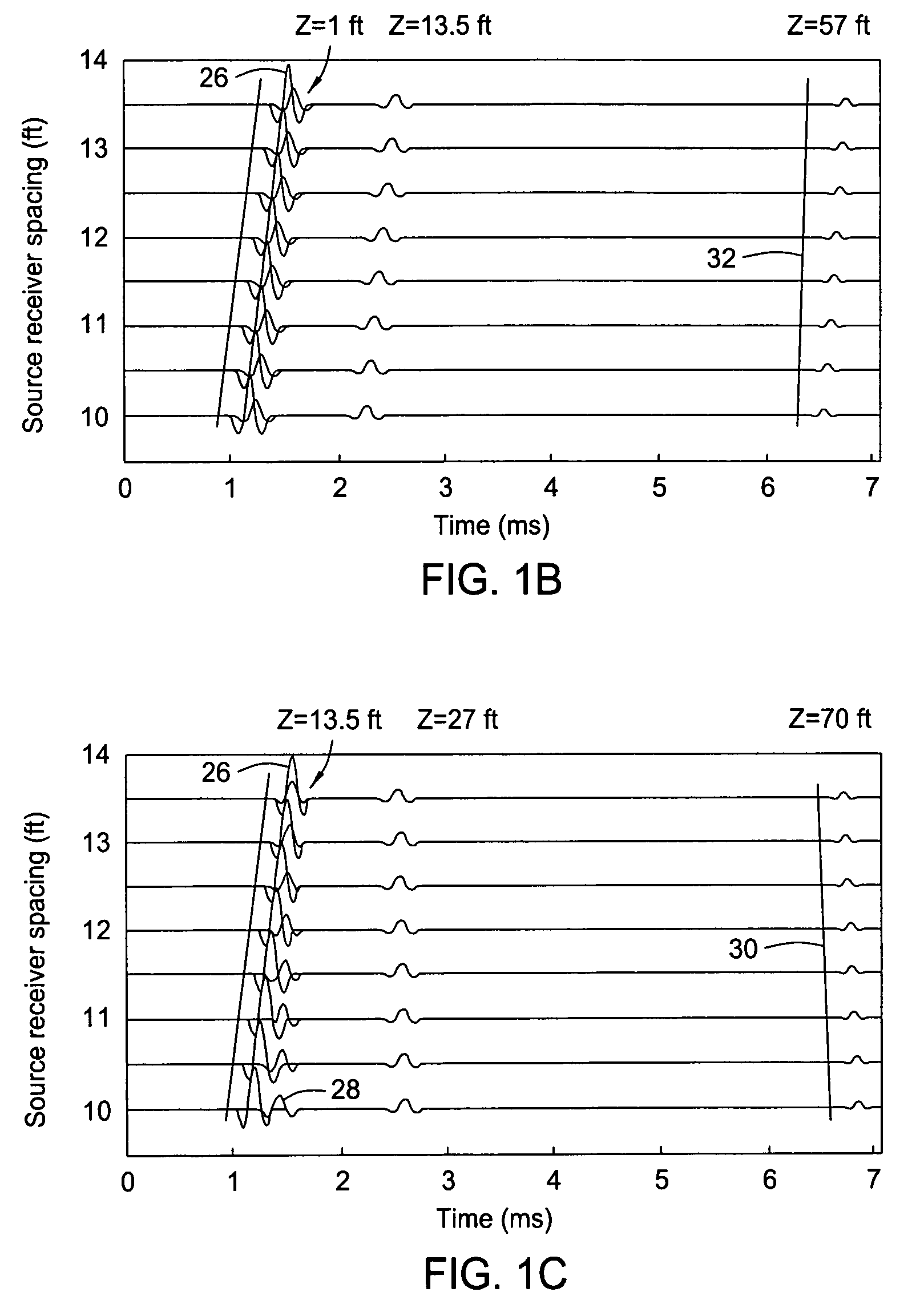
[0009]The present method disclosed herein includes analyzing acoustic data obtained from a geological formation by estimating direct wave data A from the acoustic data W from the moveout information E of the direct wave data then subtracting the direct wave data A from the acoustic data W thereby obtaining residual data R. The geological formation contains a geological bed boundary. The residual data R contains reflection wave data. They may be obtained by upwardly motivating a signal transmitter within the borehole, transmitting a series of signals into a geological formation from the signal transmitter, and receiving the signals propagating from the signal transmitter with a receiver. In order to correctly obtain data recorded above a geological bed boundary, the distance between the signal transmitter and the receiver should be reduced between successive signals. Reducing the distance between the signal transmitter and the receiver between successive signals enhances the moveout difference between the direct signals and the reflected signals. Optionally, the residual wave data R can be enhancement stacked to obtain reflected data.

Problems solved by technology

The drilling of horizontal or deviated wellbores can create some difficulties of downhole imaging due to bed boundaries or dipping beds that are encountered downhole.
Often the data received and recorded by such arrays can include unwanted signals that intermingle with the desired data and distort the final recordings thereby providing skewed results.
However, the depth that these devices can monitor within the formation is limited and they typically do not provide bed boundary or dipping bed information.

Method used


Image

  • Method for processing acoustic reflections in array data to image near-borehole geological structure
  • Method for processing acoustic reflections in array data to image near-borehole geological structure
  • Method for processing acoustic reflections in array data to image near-borehole geological structure

Examples


Embodiment Construction

[0024]Disclosed herein is a method and apparatus for obtaining an image of geological structures in the near borehole formation by using acoustic reflections from these structures. The reflections are usually small and often indiscernible in the background of overwhelming acoustic waves that travel directly along the borehole and thus need to be properly analyzed and enhanced for utilization in the imaging application. The method disclosed herein includes two primary steps. The first is a wave separation step that separates the reflections from the direct waves according to their moveout difference in an acoustic array. The second step enhances the reflections by stacking them along the reflection time moveout in the acoustic array using a priori information about a structural dip or bed inclination in the formation.

[0025]The acoustic array disclosed herein is configured so that the reflections and the direct waves have the maximum possible moveout difference. Based on this criterio...


PUM


Abstract

A method and apparatus for enhancing the moveout between a direct wave and a reflected wave. The method involves transmitting imaging signals into a body to be imaged and receiving the resulting signals propagated from the signal source. The step of receiving the propagated signals includes selectively adjusting the distance between the signal source and the signal receivers between successive signals. The method further comprises separating the reflected signals from the total received signals and enhanced stacking of the measured reflected signals.

Description

RELATED APPLICATIONS[0001]This application claims priority from co-pending U.S. Provisional Application No. 60 / 731,977, filed Oct. 31, 2005, the full disclosure of which is hereby incorporated by reference herein.BACKGROUND OF THE INVENTION[0002]1. Field of the Invention[0003]The present invention relates to a method and system of collecting and processing signal data. More specifically, the present invention relates to a method and system for enhancing a reflection wave signal in the background of a direct wave.[0004]2. Description of Related Art[0005]To obtain hydrocarbons such as oil and gas, boreholes or wellbores are drilled through hydrocarbon-bearing subsurface formations. The drilling of horizontal or deviated wellbores can create some difficulties of downhole imaging due to bed boundaries or dipping beds that are encountered downhole. To overcome this problem three dimensional borehole profiles have been developed. These three dimensional borehole profiles can change direct...

Claims


Application Information

Patent Timeline
Patent Type & Authority Patents(United States)
IPC IPC(8): G01V1/44G01V1/48G01V1/50
CPCG01V1/28G01V1/30G01V1/44G01V2210/54G01V1/34G01V1/50
Inventor TANG, XIAO MINGZHENG, YIBINGPATTERSON, DOUGLAS J
Owner BAKER HUGHES INC
Learn More