Generation of a desired wavefront with a plurality of phase contrast filters

a phase contrast filter and wavefront technology, applied in the direction of optical instruments, character and pattern recognition, instruments, etc., can solve the problem of remaining unutilized parts of filters, and achieve the effect of facilitating the use of arrays of sources

Inactive Publication Date: 2009-02-17
DANMARKS TEKNISKE UNIV
View PDF6 Cites 23 Cited by
  • Summary
  • Abstract
  • Description
  • Claims
  • Application Information

AI Technical Summary

Benefits of technology

[0083]It is an important advantage of the invention that utilisation of arrays of sources is facilitated in that the positioning and / or shapes of the phase shifting regions of the phase filter may be matched to the geometry of the source. For example, if a linear array of VCSELs forms the source, the phase shifting regions of the spatial phase filter form a corresponding linear array of phase shifting regions, each of the regions being positioned at the zero-order diffraction region of a respective VCSEL in the VCSEL array. Further, the shape of each phase shifting region may match the shape of the zero-order diffraction region of the respective VCSEL.
[0084]Likewise, a phase filter may match a source with a specific geometrical shape with a continuous phase shifting region covering an area of the phase filter that corresponds to the zero-order diffraction region of the source.
[0085]Thus, the energy of the electromagnetic fields of the system may be distributed over a large area compared to the area of a zero-order diffraction region of a single plane electromagnetic field of a known phase contrast imaging system.
[0086]Thus, the phase shifting regions of the spatial phase filter may form a rectangular array, a circular array, a linear array, two linear crossing arrays, a continuous region, a ring, etc.
[0087]The at least two substantially plane electromagnetic fields with different axes of propagation may be generated in a time multiplexed manner, e.g. by a scanning mirror or prism, deflecting or reflecting a beam of electromagnetic field in different directions of propagation.
[0088]The capability of handling high energy levels of electromagnetic fields of the present invention may be utilized for provision of a laser cutter comprising a system according to the present invention.

Problems solved by technology

Further, the spatial phase filter according to the known method processes an incident electromagnetic field in the very small diffraction region only, e.g. the zero-order diffraction region, leaving the remaining part of the filter un-utilized.

Method used


Image

  • Generation of a desired wavefront with a plurality of phase contrast filters
  • Generation of a desired wavefront with a plurality of phase contrast filters
  • Generation of a desired wavefront with a plurality of phase contrast filters

Examples


Embodiment Construction

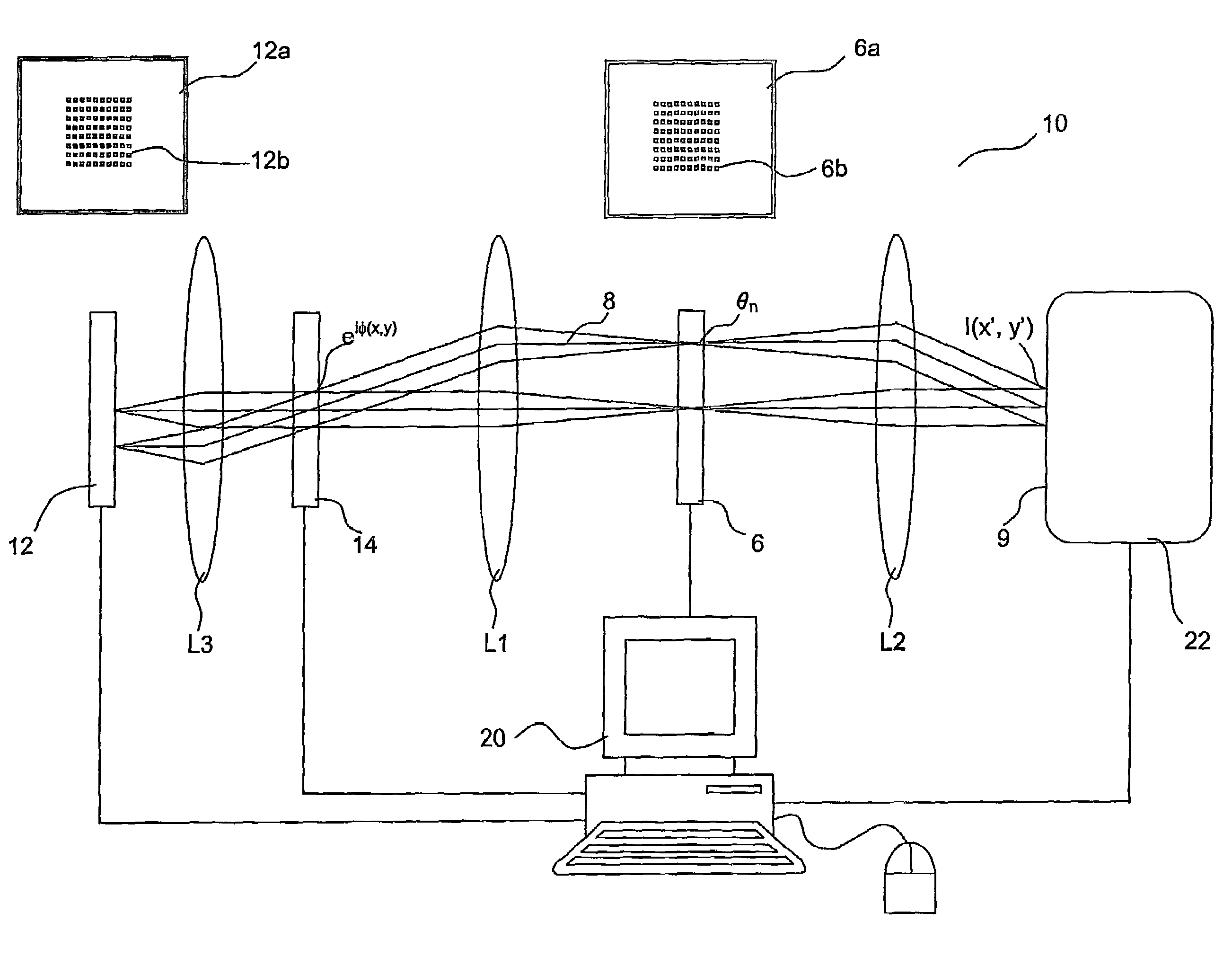
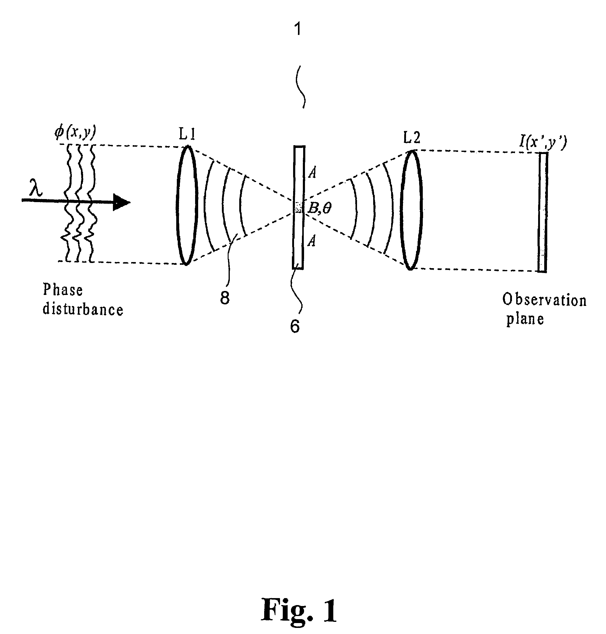
[0151]FIG. 1 shows a known phase contrast imaging system embodied in a 4f common path interferometer 1. A laser emits a light beam, which is expanded by a beam expander into a plane light wave of uniform intensity and directs it towards a phase modifying element. The light beam is transmitted through the phase modifying element and a Fourier transforming lens (L1). The phase modifying element is positioned in the front focal plane of the lens (L1) and a spatial phase filter 6 is positioned in the back focal plane of the lens L1 that is also the front focal plane of a lens L2. The Fourier transforming lenses L1, L2 need not have identical focal lengths. Different focal lengths lead to a magnification ratio different from one. The spatial phase filter 6 phase shifts by θ, and optionally attenuates (by a factor B), the zero order diffraction part 8 of the light modulated by the phase modifying element. Optionally, the remaining diffraction part of the light modulated by the phase modif...


PUM


Abstract

The present invention relates to a method and a system for synthesizing an intensity pattern based on generalized phase contrast imaging. The phase filter contains a plurality of phase shifting regions that is matched to the layout of a light source array, each of the regions being positioned at the zero-order diffraction region of a respective element of the array. Further, the shape of each phase shifting region may match the shape of the zero-order diffraction region of the respective element. Thus, the energy of the electromagnetic fields of the system may be distributed over a large area compared to the area of a zero-order diffraction region of a single plane electromagnetic field of a known phase contrast imaging system.

Description

CROSS-REFERENCE TO RELATED APPLICATIONS[0001]This application is the national phase under 35 U.S.C. 371 of PCT International Application No. PCT / DK2004 / 000452 which has an international filing date of Jun. 25, 2004, and also claims priority under 35 U.S.C. 119 to Danish application PA 2003 00966 filed on Jun. 23, 2003, both of which applications are hereby incorporated by reference in their entirety for all purposes as if fully set forth herein.FIELD OF THE INVENTION[0002]The present invention relates to a method and a system for synthesizing a prescribed intensity pattern based on generalized phase contrast imaging.BACKGROUND OF THE INVENTION[0003]It is well known to form an image by phase contrast imaging methods in which phase modulation of light is converted into intensity modulation. As opposed to intensity modulation, phase modulation does not involve loss of energy.[0004]A generalized phase contrast imaging method and system is disclosed in International Patent Application Pu...

Claims


Application Information

Patent Timeline
Patent Type & Authority Patents(United States)
IPC IPC(8): G06K9/76G02B27/09G02B27/46G02B27/52
CPCG02B27/09G02B27/46G02B27/52
Inventor GLUCKSTAD, JESPER
Owner DANMARKS TEKNISKE UNIV
Why Eureka
Try Eureka