Receiving and sending method of mobile TV phone and mobile TV phone terminal

a mobile tv phone and receiving and sending technology, applied in the field of mobile tv phone terminals, can solve the problems of troublesome operation and ineffective use of original tv phone functions, and achieve the effect of simple operation

Active Publication Date: 2009-02-17
APPLE INC
View PDF13 Cites 10 Cited by
  • Summary
  • Abstract
  • Description
  • Claims
  • Application Information

AI Technical Summary

Benefits of technology

[0011]It is an object of the present invention to provide mobile radio phone terminal for realizing a TV phone by an image and a character message by relatively simple method and operation in a manner mode in consideration of the above problems.

Problems solved by technology

However, according to this method, image data with the large amount of data needs to be sent as an email via an email server, and there is a problem that the original TV phone function is not effectively used.
The operation is troublesome that the email address of the receiver needs to additionally be inputted.

Method used


Image

  • Receiving and sending method of mobile TV phone and mobile TV phone terminal
  • Receiving and sending method of mobile TV phone and mobile TV phone terminal
  • Receiving and sending method of mobile TV phone and mobile TV phone terminal

Examples


first embodiment

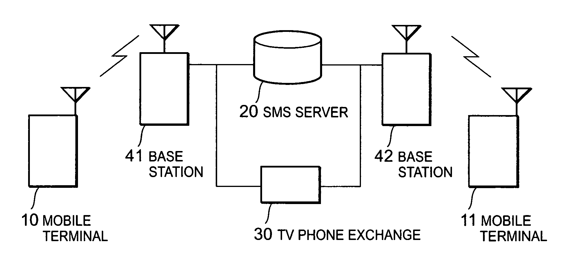
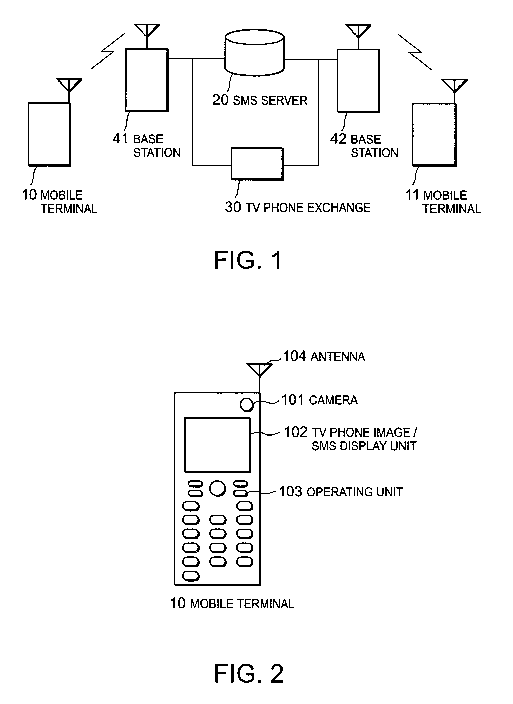
[0031]FIG. 1 is a diagram showing the entire structure of a mobile TV phone system according to the present invention. In FIG. 1, the mobile TV phone system comprises mobile TV phone terminals 10 and 11, an SMS server 20, a TV phone exchange 30, and base stations 41 and 42.

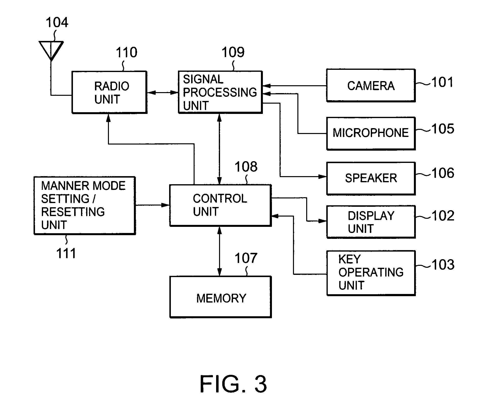
[0032]FIGS. 2 and 3 are an outline diagram and a block diagram showing examples of the mobile TV phone terminals 10 and 11 having a TV phone function and an SMS function according to the first embodiment, respectively. In FIGS. 2 and 3, each of the mobile TV phone terminals 10 and 11 comprises a camera 101, a TV phone image / SMS display unit 102, an operating unit 103, an antenna 104, a microphone 105, a speaker 106, a memory 107, a control unit 108, a signal processing unit 109, a radio unit 110, and a manner mode setting / resetting unit 111.

[0033]The control unit 108 reads various control programs stored in the memory 107 in accordance with an instruction from the operating unit 103, and controls operations of the...

third embodiment

[0058] the mobile phone includes the TV phone function, a function for converting the character data into a voice signal and sending the converted voice signal, and a function for converting the received voice signal into the character data. In the communication of TV phone in the manner mode, the converting function of the voice and the character data starts, thereby executing the communication using the character message.

[0059]When the call is sent to the mobile TV phone terminal 11 from the mobile TV phone terminal 10 in the manner mode, the function for converting the character data into the voice data and sending the voice data and the function for converting the received voice data into the character data simultaneously start together with the TV phone function. The character data inputted from the key input unit 103 in the mobile TV phone terminal 10 is converted into the voice signal by the function for converting the character data into the voice, and is sent to the mobile ...


PUM


Abstract

A unit for realizing a TV phone by using an image and a character message by a relatively simple method in a manner mode is provided. In the manner mode of one mobile TV phone terminal, a control unit for controlling the operation of the one mobile TV phone terminal prohibits the sound input via a microphone of the one mobile TV phone terminal and the sound output via a speaker and operates an SMS function with a TV phone function. A line between the one mobile TV phone terminal and another one is connected, an SMS message is created by operating a key input unit of the one mobile TV phone terminal, and a send key is pressed. Then, the message data is sent to the other mobile TV phone terminal via one base station, an SMS server, and another base station. A display unit of the other mobile TV phone terminal displays the message together with the image sent via a TV phone exchange.

Description

[0001]This application claims priority to prior Japanese Patent Application No. 2004-112357 filed Apr. 6, 2004, the disclosure of which including specification, drawings and claims is incorporated herein by reference in its entirety.BACKGROUND OF THE INVENTION[0002]1. Field of the Invention[0003]The present invention relates to a mobile television (TV) phone terminal, and more particularly, to a receiving and sending method of a mobile TV phone and a mobile TV phone terminal in a manner mode.[0004]2. Description of the Related Art[0005]Recently, a mobile phone with a TV function has been spread. For example, Japanese Unexamined Patent Application Publication (JP-A) No. 6-292195 (Patent Document 1) discloses a mobile radio TV phone, in which a phone number of a receiver, or a called party, is inputted from a key operating unit of a main body of a mobile terminal device while visually checking it on a display unit of a liquid crystal monitor. A call is generated by sending a radio sig...

Claims


Application Information

Patent Timeline
Patent Type & Authority Patents(United States)
IPC IPC(8): H04M1/00H04M1/72436H04N7/14H04M1/72439H04M11/00H04W4/12H04W4/18H04W88/02
CPCH04M1/72552H04M1/72555H04N7/141H04N21/41407H04N21/4788H04M1/72439H04M1/72436
Inventor HIMENO, YASUHIRO
Owner APPLE INC
Why Eureka
Try Eureka