
Fill-through tire pressure indicator

a fill-through tire and indicator technology, applied in the field of pressure indicators, can solve the problems of not revealing the use of a free moving diaphragm, operating inconsistently and inaccurately, and other devices mentioned in the prior art are not as likely to provide an airtight seal under high pressure, so as to reduce improve the effect of tire separation, and facilitate the proper inflated tir

Active Publication Date: 2009-02-24
RIGHTPSI
View PDF24 Cites 20 Cited by
  • Summary
  • Abstract
  • Description
  • Claims
  • Application Information

AI Technical Summary

Benefits of technology

"The present invention is a pressure indicator that can be used for automobile tires and other inflatable articles. It is designed to indicate whether the tire pressure is within a predetermined range, above or below. The indicator has three bands or sections that change color to indicate the pressure range. The indicator is easy to see, can be used without removing the pressure indicator, and helps improve safety and performance. It can reduce expenses and waste, minimize damage to tires, and help maintain proper tire temperature and design. The invention also helps ensure proper tire inflation for maximum interphase footprint, improves load management and weight bearing, and complies with safety regulations. It is affordable, reliable, and effective in achieving its intended purposes."

Problems solved by technology

1. The prior art cited does not disclose the use of a free moving diaphragm with a center hole that allows air to pass through the plane of the diaphragm.
Other devices mentioned in the prior art are not as likely to provide an airtight seal under high pressure.
Furthermore, non-diaphragm based indicators will likely have varying friction caused by their sealing surfaces, meaning that they will operate inconsistently and inaccurately.
2. The prior art cited does not disclose the use of a mirror to allow an indicator to be viewed from more angles.

Method used


Image

  • Fill-through tire pressure indicator
  • Fill-through tire pressure indicator
  • Fill-through tire pressure indicator

Examples


Embodiment Construction

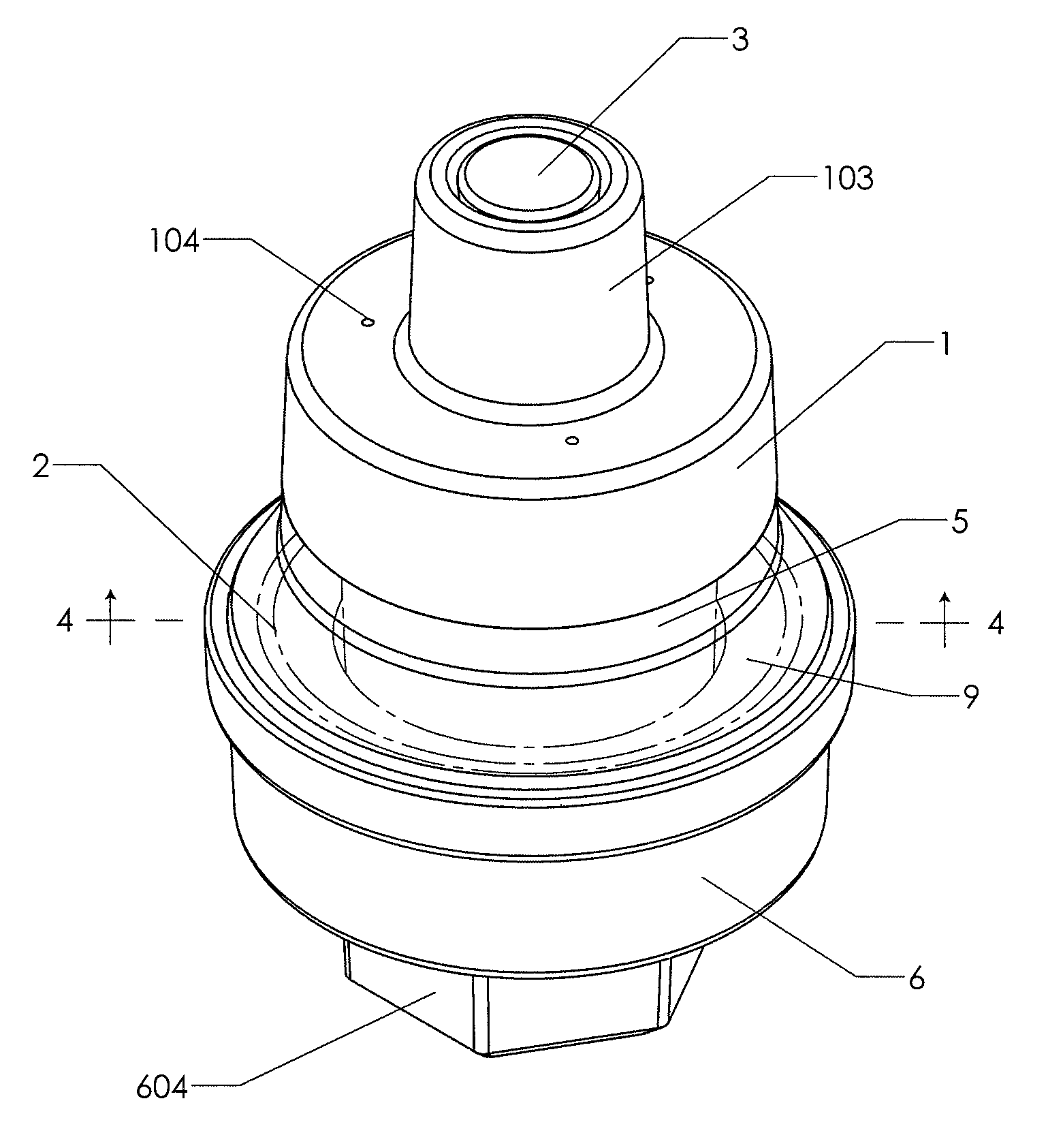
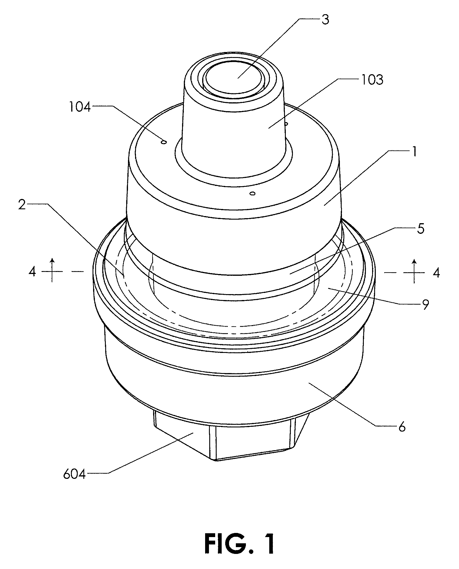
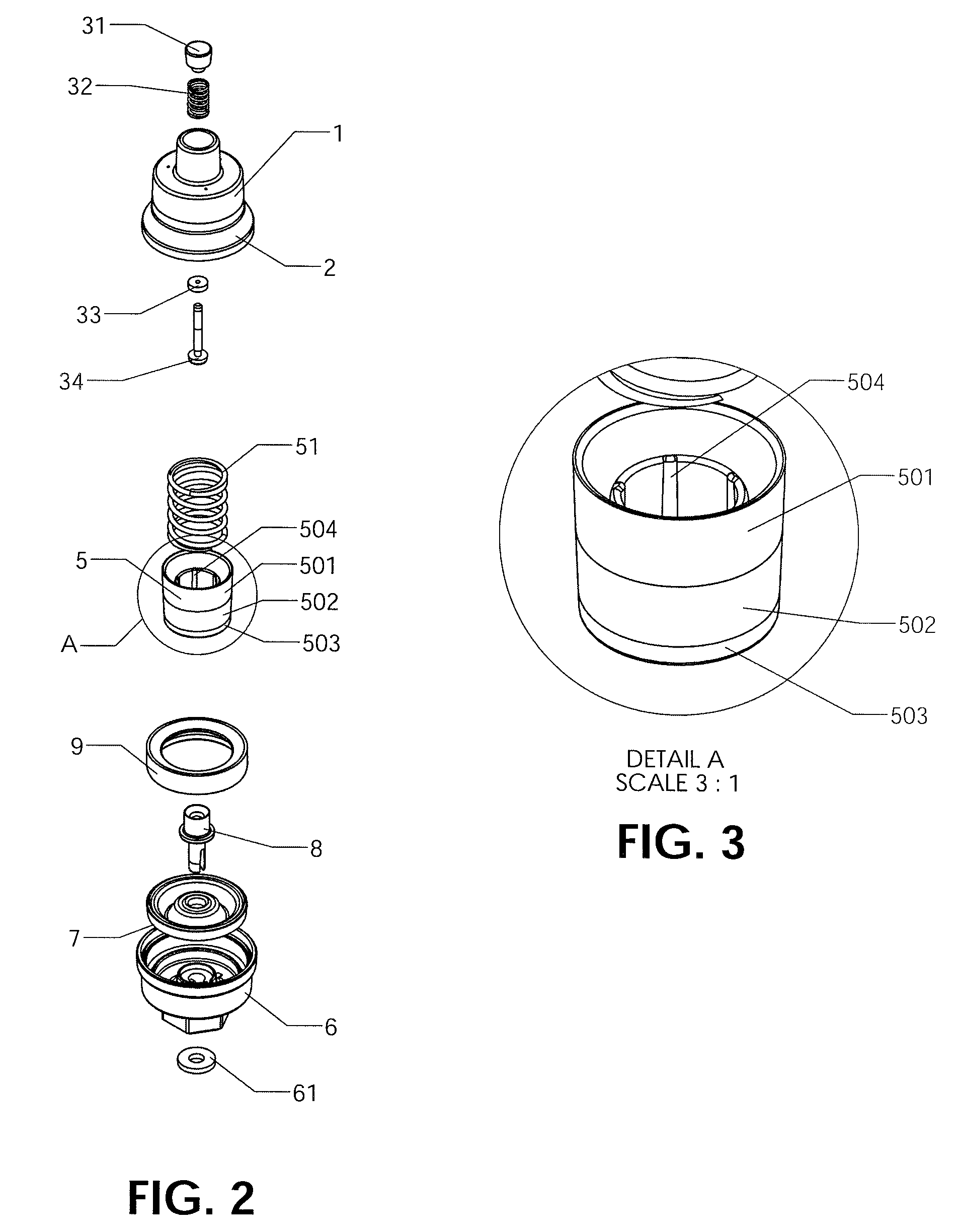
[0057]The present invention is a fill-through pressure indicator for tires (or other inflatable objects), which in its preferred embodiment is a tire stem attachment with a pressure indication sleeve concentric to a fill valve. The following parts are shown in the drawings:

[0058]1 Top Case

[0059]101 Triangular Extensions

[0060]102 Hole in Top Case

[0061]103 Extension in Top Case

[0062]104 Vent Holes in Top Case

[0063]105 Inside of Top Case

[0064]107 Ambient Air Pressure Chamber

[0065]108 Main Chamber

[0066]109 Fill Chamber

[0067]2 Lens

[0068]3 Valve Pin Assembly

[0069]31 Valve Pin Top

[0070]32 Valve Pin Spring

[0071]33 Valve Pin Seal

[0072]34 Valve Pin Bottom

[0073]341 Shoulder of Valve Pin Bottom

[0074]5 Slider

[0075]51 Slider Spring

[0076]501 Orange Section

[0077]502 Black Section

[0078]503 Yellow Section

[0079]504 Bearing Rails

[0080]6 Base

[0081]61 Schrader Valve Seal

[0082]601 Ribs

[0083]602 Center Pin Alignment Tab

[0084]603 Slot

[0085]604 Hexagonal Extension

[0086]605 Tire Stem Threads

[0087]7 Diaphragm

[...


PUM


Abstract

A tire pressure indicator that is combined with a fill valve. The indicator and the fill valve are coaxial or concentric. The invention may be screwed onto a tire valve stem. The indicator has three bands or sections, each of which is a different color, for indicating whether tire pressure is within a predetermined range, above that range, or below that range. The colors are viewed through a lens, aided by a mirror. A diaphragm pushes the indicator up when pressure rises, while a spring pushes the indicator down when pressure drops. A tire may be inflated or deflated while the invention is mounted on a tire stem. During inflation, the pin in an air chuck at the end of an air hose may depress a valve pin assembly to open the fill valve. A user may deflate the tire by manually depressing the valve pin assembly to release air.

Description

BACKGROUND OF THE INVENTION[0001]1. Field of the Invention[0002]The present invention relates to pressure indicators combined with fill valves.[0003]The motoring public is generally aware of the need to have tire properly inflated for optimum tire life and performance. Under-inflated tires (or over-inflated tires) wear more quickly and degrade the handling characteristics of a motor vehicle. The tedium of measuring the pressure in each tire causes many drivers to forego measuring the pressure in their tires and to rely on a visual inspection. However, mere visual inspection is inadequate, particularly when a car has radial tires, because a sidewall bulge is present even in properly inflated tires. The importance of properly inflated tires was acknowledged by the federal government with the passage of the TREAD Act. It mandates cars have a tire pressure management system. These are electrical in nature and it would be an advantage to have tire pressure indication that is independent ...

Claims


Application Information

Patent Timeline
Patent Type & Authority Patents(United States)
IPC IPC(8): B60C23/02
CPCB60C23/0496
Inventor MILANOVICH, PHILIP JOHNMILANOVICH, JOHN KOSTINSTRASSER, MICHAEL JURGENSLONE, CLINTON NEALTAMMEN, WILLIAM GREGORY
Owner RIGHTPSI
Learn More