Digital single-lens reflex camera

a digital single-lens, reflex camera technology, applied in the field of digital single-lens reflex cameras, can solve the problems of vignetting cannot be effectively prevented is difficult to prevent vignetting from occurring by using only the micro lens, so as to prevent deterioration of image quality

Inactive Publication Date: 2009-02-24
RICOH IMAGING COMPANY
View PDF9 Cites 8 Cited by
  • Summary
  • Abstract
  • Description
  • Claims
  • Application Information

AI Technical Summary

Benefits of technology

[0007]Therefore, an object of the present invention is to provide a digital single-lens reflex camera which enables images to be corrected based on the combination of an interchangeable lens and an imaging device, and to prevent deterioration of the quality of the images.
[0008]A first digital single-lens reflex camera according to the present invention, includes a lens unit and a camera body. The lens unit has a photographing lens and an identification data memory for storing identification data to identify the photographing lens. The camera body to which the lens unit is detachably attached, has an imaging device which receives light transmitted through the photographing lens to generate an image corresponding to a subject, a lens data memory for storing lens data that indicates the shading characteristics of the photographing lens, a lens data reader that reads the lens data based on the identification data, and an image corrector that corrects an error in the image of the subject caused by shading, based on the lens data read by the lens data reader and imaging device data that indicates the shading characteristics of the imaging device.
[0015]A third camera body according to the present invention, to which a lens unit having a photographing lens and an identification data memory for storing identification data to identify the photographing lens, and a storage medium for storing lens data that indicates the shading characteristics of the photographing lens, are detachably attached, includes an imaging device which receives light transmitted through the photographing lens to generate an image corresponding to a subject, a lens data memory for storing lens data that indicates the shading characteristics of the photographing lens, a lens data reader that reads the lens data based on the identification data, and an image corrector that corrects an error in the image of the subject caused by shading, based on the lens data read by the lens data reader and imaging device data that indicates the shading characteristics of the imaging device.
[0016]A third storage medium according to the present invention, is for storing lens data that indicates the shading characteristics of a photographing lens. The third storage medium is detachably attached to a camera body to which a lens unit having the photographing lens and an identification data memory for storing identification data to identify the photographing lens is detachably attached, and the camera body having an imaging device which receives light transmitted through the photographing lens to generate an image corresponding to a subject, a lens data reader that reads the lens data, and an image corrector that corrects an error in the image of the subject caused by shading, based on the lens data read by the lens data reader and imaging device data that indicates the shading characteristics of the imaging device.

Problems solved by technology

Generally, micro lenses are provided on an imaging device, however, it is difficult to prevent vignetting from occurring by using only the micro lenses.
Especially, in the case where the imaging device has many pixels,an vignetting can not be corrected by using only the micro lenses, because the area of the photo diodes is small relative to a distance between micro lenses and the photo diodes.
Therefore, shading correction based on only the characteristics of a photographing lens, sometimes can not effectively prevent deterioration of the image quality.

Method used


Image

  • Digital single-lens reflex camera
  • Digital single-lens reflex camera
  • Digital single-lens reflex camera

Examples


first embodiment

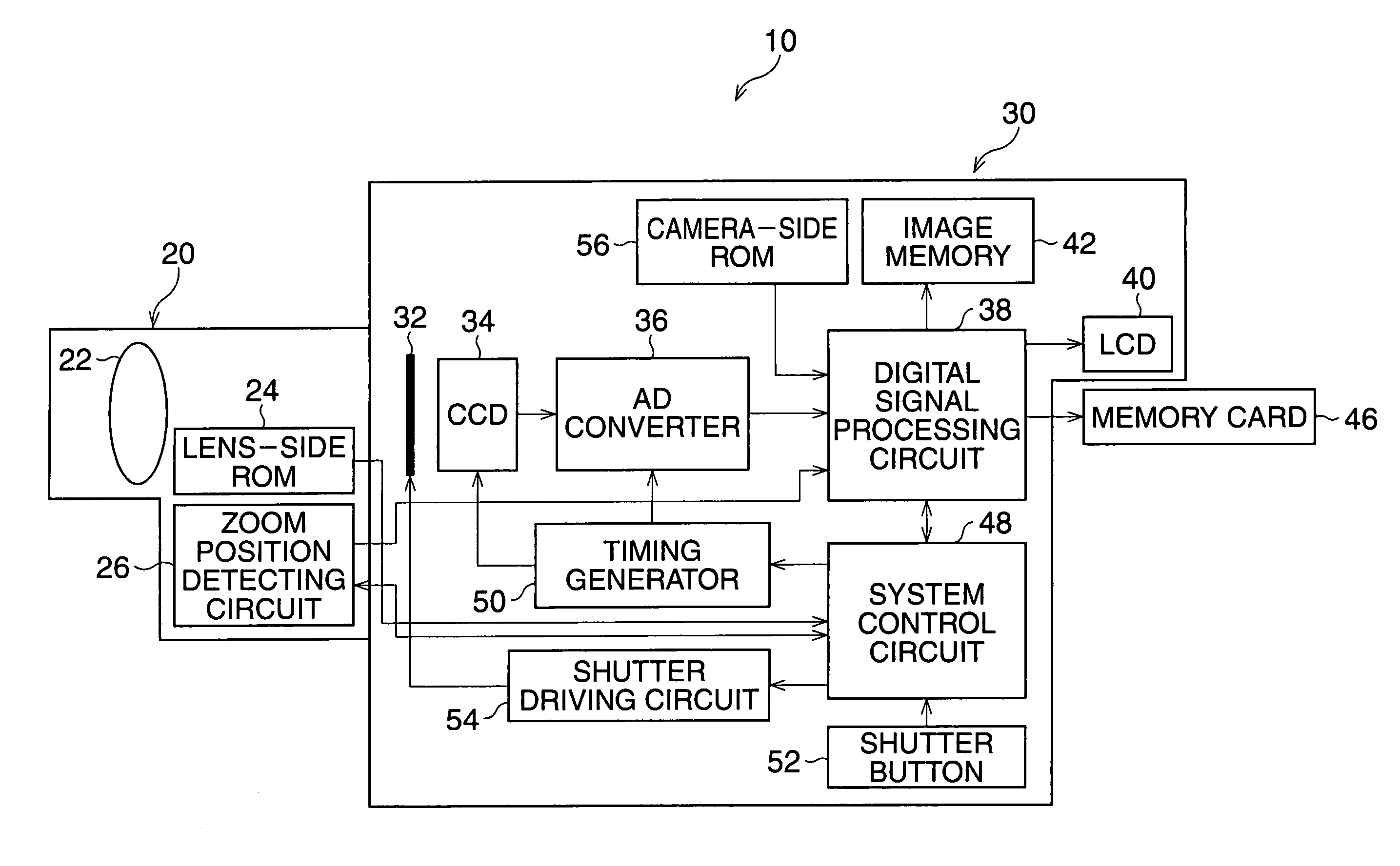
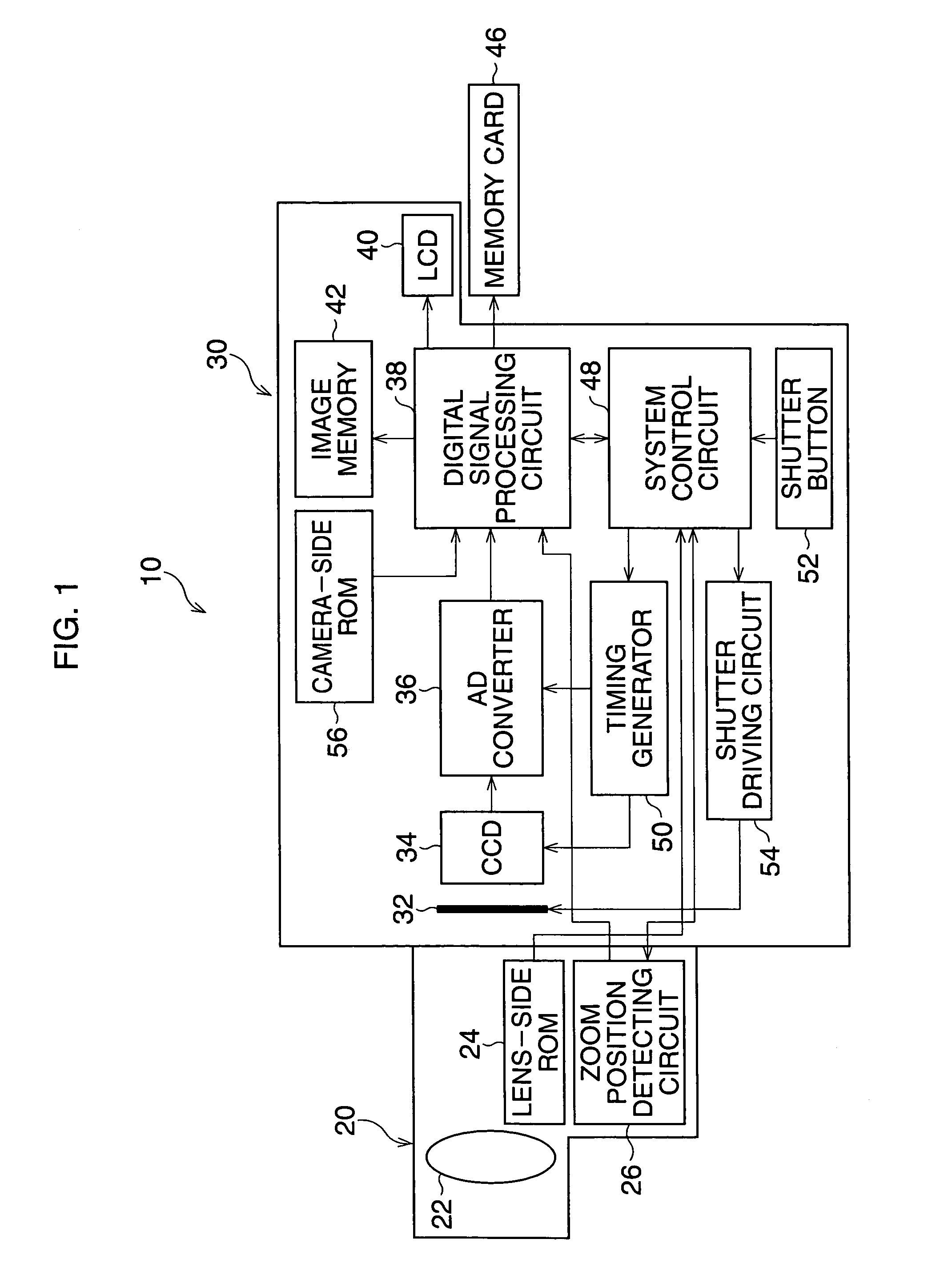
[0034]Hereinafter, the preferred embodiments of the present invention are described with reference to the attached drawings. FIG. 1 is a block diagram of the digital single-lens reflex camera of the

[0035]A digital single-lens reflex camera 10 includes a lens unit 20 having a photographing lens 22 of a zoom lens, and a camera body 30 to which the lens unit 20 is detachably attached. A plurality of lens units including the lens unit 20, can be attached to the camera body 30. The lens unit 20 has a lens-side ROM 24 for storing identification data to identify the photographing lens 22, and a zoom position detecting circuit 26 to detect a zoom position of the photographing lens 22 and transmit zoom position data (focal distance data) indicating the zoom position of the photographing lens 22, to the camera body 30. Further, in the lens unit 20, an aperture position detecting circuit (not shown) to detect an aperture position and transmit aperture position data indicating the aperture posi...

second embodiment

[0055]FIG. 14 is a block diagram of the digital single-lens reflex camera 10 of the

[0056]In this embodiment, there are the following differences from the first embodiment. The lens unit 20 can be attached to and used with a plurality of camera bodies including the camera body 30, and the lens data is stored in the lens unit 20, not in the camera body 30. The lens data is stored in the lens-side ROM 24 with the identification data, and the lens data is stored as full data set. Therefore, when the lens unit 20 is attached to a camera body whose imaging device has the largest format size of the imaging devices included in the camera bodies which can be used with the lens unit 20, such as the camera body 30, the lens data can be used.

[0057]The digital signal processing circuit 38 selectively reads a part of, or all of the lens data stored in the lens-side ROM 24 according to the format size of the CCD 34, and stores the read lens data in the RAM 58. Further, the digital signal processin...

third embodiment

[0065]FIG. 16 is a block diagram of the digital single-lens reflex camera 10 of the

[0066]In this embodiment, there are the following differences from the first and second embodiments. The lens data is stored in the memory card 46, and an EEPROM 62 is provided in the camera body 30 instead of the camera-side ROM 56 and RAM 58. The lens data is read by the digital signal processing circuit 38 from the memory card 46, and stored in the EEPROM 62. The digital signal processing circuit 38 selectively reads the lens data of the photographing lens 22 currently used among the lens data stored in the EEPROM 62, based on the identification data of the photographing lens 22. Further, the digital signal processing circuit 38 reads the imaging device data from the memory 60 in the system control circuit 48, and calculates shading data from the lens data of the photographing lens 22 and imaging device data.

[0067]In this third embodiment, the EEPROM 62 is not necessarily needed. When the EEPROM 62...


PUM


Abstract

A digital single-lens reflex camera includes a lens unit and a camera body. The lens unit has a photographing lens and an identification data memory for storing identification data to identify the photographing lens. The camera body, to which the lens unit is detachably attached, has an imaging device which receives light transmitted through the photographing lens to generate an image corresponding to a subject, a lens data memory for storing lens data that indicates the shading characteristics of the photographing lens, a lens data reader that reads the lens data based on the identification data, and an image corrector that corrects an error in the image of the subject caused by shading, based on the lens data read by the lens data reader and imaging device data that indicates the shading characteristics of the imaging device.

Description

BACKGROUND OF THE INVENTION[0001]1. Field of the Invention[0002]The present invention relates to a digital single-lens reflex camera where the lens is exchangeable, especially it relates to a digital single-lens reflex camera which can improve the quality of a photographed image.[0003]2. Description of the Related Art[0004]Recently, the usage of digital single-lens reflex cameras has been gradually expanding, replacing the current silver-halide film single-lens reflex cameras. Generally, in an interchangeable lens for a digital single-lens reflex camera, to identify the photographing lens, identification data and so on are stored. And when the interchangeable lens is attached to the camera body, the identification data and so on are transmitted to the camera body.[0005]Lens exchangeable cameras having data to correct shading and so on for their interchangeable lenses, the data being stored in the interchangeable lens, the camera body, or a storage medium, are known. In these cameras...

Claims


Application Information

Patent Timeline
Patent Type & Authority Patents(United States)
IPC IPC(8): G03B17/00G03B7/20G03B17/14H04N5/243H04N5/335H04N5/361H04N5/369H04N5/372H04N101/00
CPCG03B17/14H04N5/232H04N5/23209H04N5/23296H04N2101/00H04N23/60H04N23/663H04N23/69
Inventor ARIMOTO, AKIRASATO, KOICHI
Owner RICOH IMAGING COMPANY
Why Eureka
Try Eureka