Graphical user interface system and method for organized network analysis

a user interface and network analysis technology, applied in the field of computer networks, can solve problems such as failure of network failures during attempts to establish links, and inability to modify requirements appropriately

Inactive Publication Date: 2009-02-24
MCAFEE LLC
View PDF12 Cites 108 Cited by
  • Summary
  • Abstract
  • Description
  • Claims
  • Application Information

AI Technical Summary

Problems solved by technology

If no agreement is reached within some reasonable period (on the order of several seconds), or an error condition occurs, the attempt to establish a link has failed.
However, for some high-speed topologies such as Gigabit Ethernet, many network failures occur during attempts to establish a link.
For example, one device may have communication requirements that are incompatible with another device, or a device may not modify its requirements appropriately in order to reach an agreement.
Most prior art protocol analyzers fail to capture any information on the training and negotiation process, requiring the use of one or more logic analyzers to capture the information as digital waveforms, and extensive effort to decode the information.
Furthermore, those prior art protocol analyzers that do capture the physical link layer handshake protocol control packet provide no merged information and no decoding or analysis, requiring a time-consuming process to troubleshoot the link failure.
Furthermore, although the frame data from both channels is merged, the auto-negotiation ordered sets for the two channels are not merged to facilitate analysis of a link failure.
Thus, a user attempting to determine why the devices failed to establish a link, using the information provided in FIGS. 5c through 5l, must go through a tedious and time-consuming process.

Method used


Image

  • Graphical user interface system and method for organized network analysis
  • Graphical user interface system and method for organized network analysis
  • Graphical user interface system and method for organized network analysis

Examples


Embodiment Construction

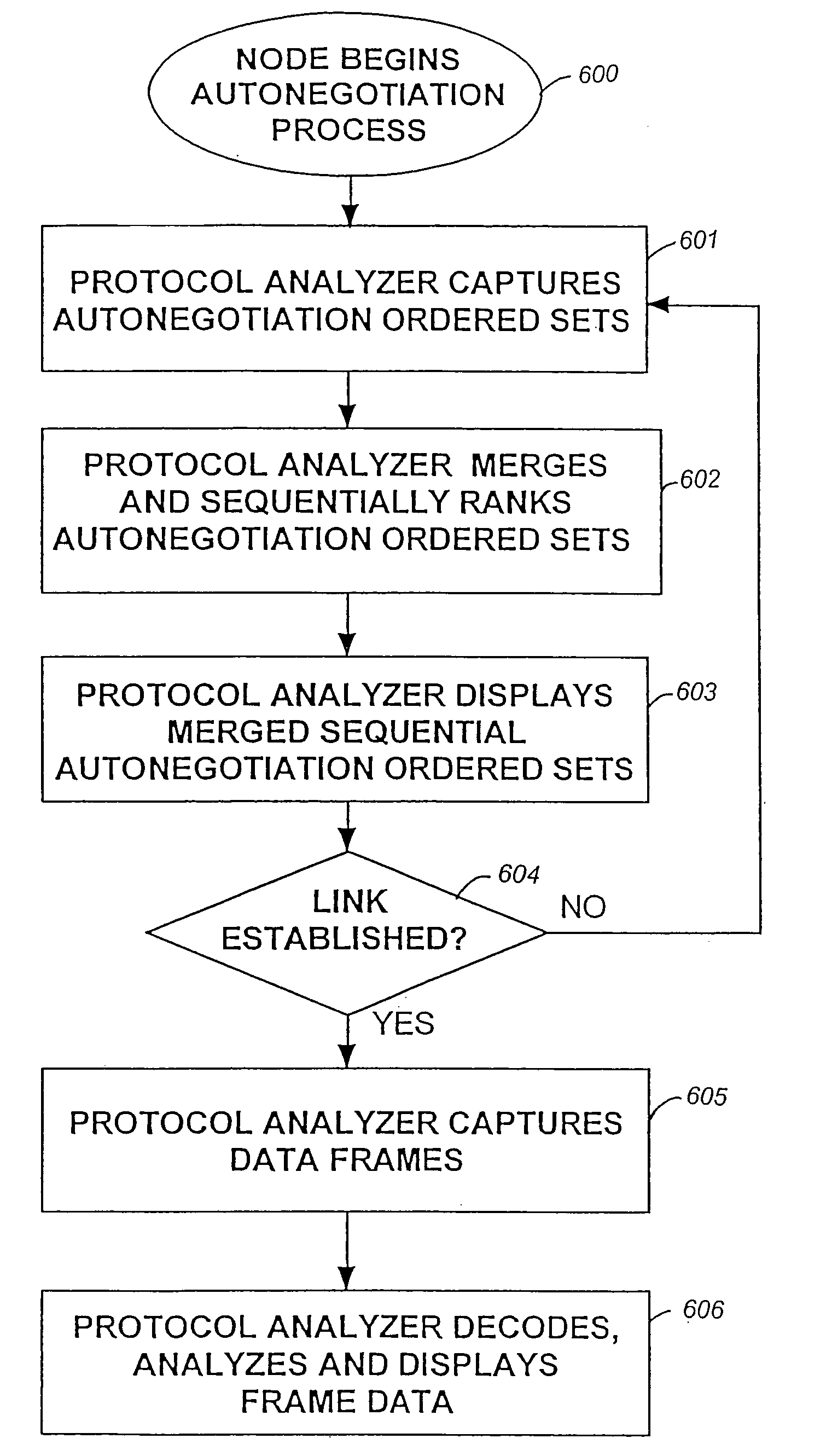
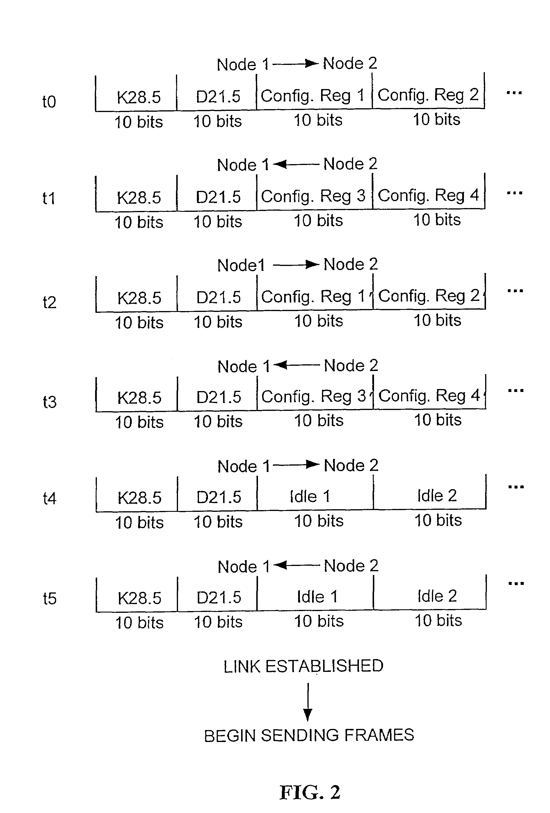
[0026]FIG. 6 shows steps for creating a merged sequential list of the auto-negotiation ordered sets generated by two nodes attempting to establish a link over Gigabit Ethernet. One node, node 1, initiates the training and negotiation process 600 by sending an auto-negotiation ordered set over channel 1, to which the other node, node 2, eventually responds over channel 2. The protocol analyzer captures each auto-negotiation ordered set 601 in a hardware capture buffer for each channel. The protocol analyzer software then traverses the capture buffer of each channel, looking for timestamps which are followed by ten-bit codes carrying the codes / C1 / or / C2 / . These codes translate to K28.5 or D21.5, for / C1 / , and K28.5 or D2.2, for / C2 / . The K prefix indicates that the code is a control code, and the D prefix indicates that the code is a data code. The software then parses the auto-negotiation ordered sets 602, using the algorithm that the smaller timestamp is selected first, and, if bo...


PUM


Abstract

A graphical user interface is provided for displaying network analysis. Included is a plurality of tabs selectable by a user. Also included is a plurality of windows each associated with one of the tabs and adapted for displaying a different aspect of a network analysis. In use, the windows are each displayed upon the selection of the associated tab.

Description

[0001]This is a Continuation application of prior application Ser. No. 10 / 224,248 filed on Aug. 19, 2002 now U.S. Pat. No. 6,810,017” which is a Continuation application of prior application Ser. No. 09 / 440,804 filed on Nov. 15, 1999 now U.S. Pat. No. 6,707,794, the disclosure of which is incorporated herein by reference.FIELD OF THE INVENTION[0002]The present invention relates to the field of computer networks. In particular, the present invention relates to a system, computer program product and method for analyzing handshake protocols for the physical link layer of a computer network.BACKGROUND OF THE INVENTION[0003]Network protocol analyzers are widely used to monitor computer network performance and assist users in analyzing the causes of network slowdowns or outages. Protocol analyzers assist in explaining possible causes for network problems, collect expert analysis data automatically, learn network configurations continuously, show breakdown of network protocol activity auto...

Claims


Application Information

Patent Timeline
Patent Type & Authority Patents(United States)
IPC IPC(8): H04L12/26H04L12/24
CPCH04L41/0631H04L41/0896H04L43/18
Inventor LEONG, PAK-TAK PATRICKWON, KING L.
Owner MCAFEE LLC
Why Eureka
Try Eureka