Charging device and image forming apparatus

a charging device and image forming technology, applied in the direction of electrographic process apparatus, instruments, corona discharge, etc., can solve the problems of limited operation life of electrophotographic apparatus, image defects, density irregularities

Inactive Publication Date: 2009-02-24
FUJIFILM BUSINESS INNOVATION CORP
View PDF9 Cites 5 Cited by
  • Summary
  • Abstract
  • Description
  • Claims
  • Application Information

AI Technical Summary

Benefits of technology

[0010]For the latter treatment, when a contact-type charging member is used for charging a photoreceptor surface, particularly when charging is carried out by superimposing of an alternating current voltage, a method to reduce the applied alternating current voltage (electric current) is suggested.

Problems solved by technology

The operating life of electrophotographic apparatuses is limited in particular by the wear of photoreceptors.
However, if a sufficient alternating current voltage is not applied, satisfactory uniform charging effect by the superimposing of the alternating current voltage cannot be achieved, which results in image defects such as density irregularity due to non-uniform charging.

Method used


Image

  • Charging device and image forming apparatus
  • Charging device and image forming apparatus
  • Charging device and image forming apparatus

Examples


example 1

(Manufacturing of Charging Roll)

—Formation of Elastic Layer—

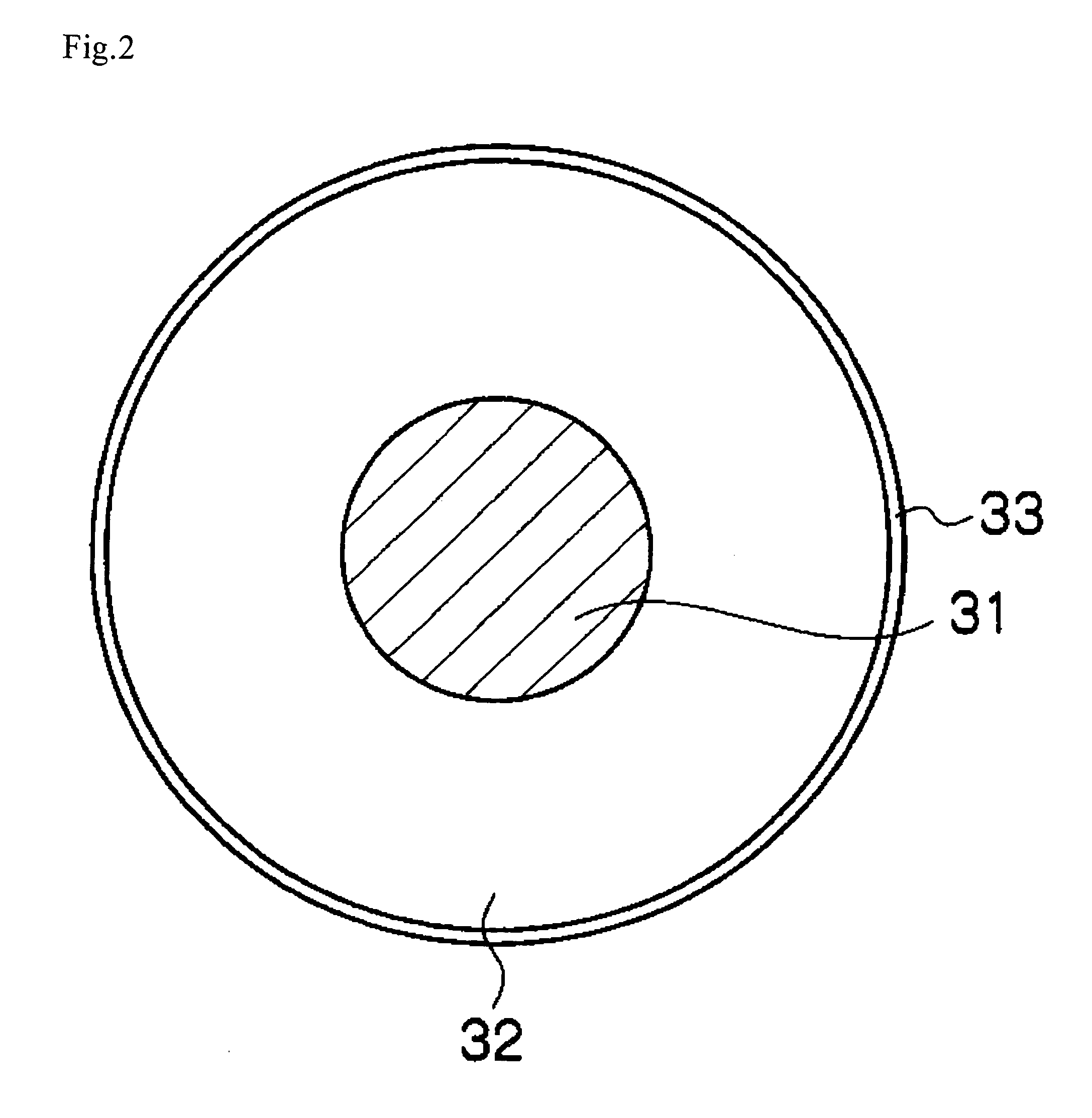
[0191]A mixture of the following composition is kneaded by an open roll mill. The mixture prepared is applied onto an adhesive layer composed of a polyolefin-based adhesive (trade name: XJ150: manufactured by Lord Far East Incorporated) on the surface of an electro-conductive support having a diameter of 9 mm and formed by SU303 stainless steel, and an elastic layer is formed with a press-molding machine in the shape of a roll having a diameter of 15 mm, and thereafter, the elastic layer is ground. Thus, an electro-conductive elastic roll A having a diameter of 14 mm is obtained.

[0192]Rubber material 100 parts by weight

[0193](Epichlorohydrin-ethylene oxide-allylglycidyl ether copolymer rubber, trade name: Gechron 3106: manufactured by Zeon Corporation)

[0194]Electro-conductive agent (carbon black, trade name: Asahi Thermal: manufactured by Asahi Carbon Co., Ltd.) 15 parts by weight

[0195]Electro-conductive agent (trade name: ...

example 2

(Manufacturing of Charging Roll)

—Formation of Elastic Layer—

[0218]An electro-conductive elastic roll B is molded as in Example 1, except that conditions for grinding and the fluctuation of the outside diameter are changed.

—Formation of Surface Layer—

[0219]A surface layer is formed and a charging roll 2 is obtained as in Example 1, except that an electro-conductive elastic roll B is used.

(Manufacturing of Photoreceptor)

[0220]A photosensitive layer is formed and a photoreceptor 2 is obtained as in Example 1.

(Evaluation)

[0221]The photoreceptor 2 is evaluated as in Example 1. The results are summarized in Table 2.

example 3

(Manufacturing of Charging Roll)

—Formation of Elastic Layer—

[0222]An electro-conductive elastic roll C is molded as in Example 1, except that conditions for grinding and the fluctuation of the outside diameter are changed.

—Formation of Surface Layer—

[0223]A surface layer is formed and a charging roll 3 is obtained as in Example 1, except that an electro-conductive elastic roll C is used.

(Manufacturing of Photoreceptor)

[0224]A photosensitive layer is formed and a photoreceptor 3 is obtained as in Example 1.

(Evaluation)

[0225]The photoreceptor 3 is evaluated as in Example 1. The results are summarized in Table 2.


PUM


Abstract

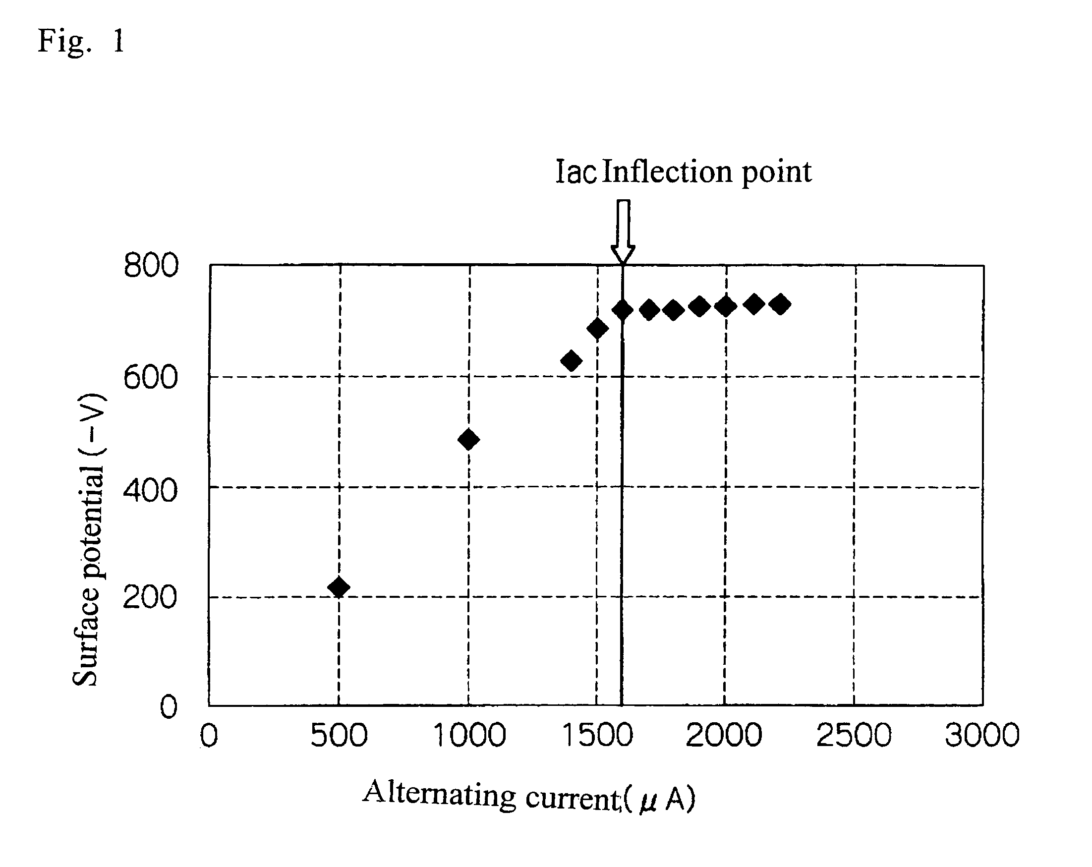
The invention provides a charging device including a charging roll and a voltage application unit which is capable of applying to the charging roll a voltage in which an alternating current voltage is superimposed on a direct current voltage, the alternating current (Iac) which flows through the charging roll satisfying the following Equation (1), the charging roll satisfying the following conditions (a) to (c), and the charging roll contacting an image supporter to charge the image supporter:Iac / I(inflection)≦1.2  Equation (1)(in the Equation (1), I (inflection) represents the flexion point of lac)(a) the fluctuation of the outside diameter is 0.1 mm or less(b) resistance (common logarithm) is 9.0 log·Ω or less(c) resistance variation (common logarithm) is 0.5 log·Ω or less.

Description

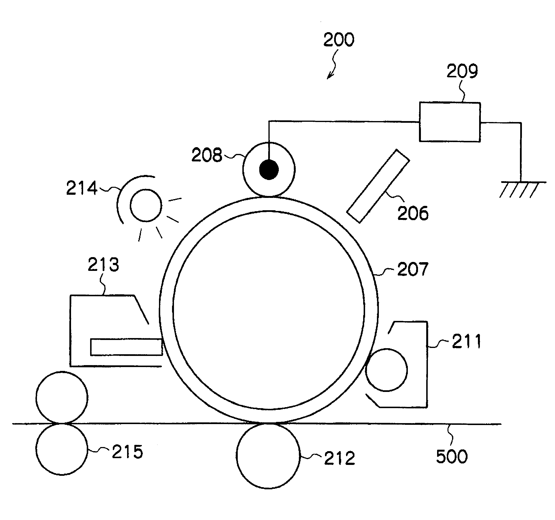
BACKGROUND[0001]1. Technical Field[0002]The present invention relates to a charging device used for electrophotographic and electrostatic recording processes, and an image forming apparatus using the charging device.[0003]2. Related Art[0004]In image forming apparatuses using electrophotographic systems, a uniform charge is formed on an image supporter (photoreceptor), an electrostatic latent image is formed thereon using a laser beam in which an image signal is modulated, and the electrostatic latent image is developed into a toner image with charged toner. Subsequently, the toner image is electrostatically transferred to a recording medium directly or through an intermediate transfer body to obtain a desired transferred image.[0005]As described above, in an image forming apparatus using an electrophotographic system, charging treatment is carried out to form a uniform charge on the image supporter. An example of the charging member for such charging treatment is a contact-type cha...

Claims


Application Information

Patent Timeline
Patent Type & Authority Patents(United States)
IPC IPC(8): G03G15/02
CPCG03G15/0233
Inventor MIURA, HIROYUKIROKUTAN, MINORUSUGA, TAKANORIODA, YUKIKO
Owner FUJIFILM BUSINESS INNOVATION CORP
Why Eureka
Try Eureka